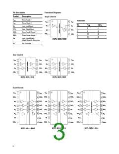
Insulation and Safety Related Specifications
Parameters
Condition
Min.
Typ.
Max.
Units
Barrier Impedance
Ω||pF
Single Channel
Dual Channel
Quad Channel
>1014||3
>1014||3
>1014||7
Creepage Distance (External)
mm
8-Pin PDIP
8-Pin SOIC
16-Pin SOIC Narrow Body
16-Pin SOIC Wide Body
7.036
4.026
4.026
8.077
Leakage Current
240 VRMS
60 Hz
0.2
µA
Absolute Maximum Ratings
Parameters
Symbol
Min.
Max.
Units
Storage Temperature
Ambient Operating Temperature[1]
Supply Voltage
TS
–55
–55
–0.5
–0.5
–0.5
–0.5
175
°C
°C
V
TA
125
VDD1, VDD2
VIN
7
Input Voltage
VDD1 +0.5
VDD2 +0.5
VDD2 +0.5
10
V
Voltage Output Enable (HCPL-9000/-0900)
Output Voltage
VOE
V
VOUT
IOUT
V
Output Current Drive
Lead Solder Temperature (10s)
ESD
mA
°C
260
2 kV Human Body Model
Notes:
1. Absolute Maximum ambient operating temperature means the device will not be damaged if operated under these conditions. It does not
guarantee performance.
Recommended Operating Conditions
Parameters
Symbol
Min.
Max.
Units
Ambient Operating Temperature
Supply Voltage
TA
–40
3.0
2.4
0
100
5.5
VDD1
0.8
1
°C
V
VDD1, VDD2
VIH
Logic High Input Voltage
Logic Low Input Voltage
Input Signal Rise and Fall Times
V
VIL
V
tIR, tIF
µs
This product has been tested for electrostatic sensitivity to the limits stated in the specifications. However, Agilent recommends that all integrated circuits
be handled with appropriate care to avoid damage. Damage caused by inappropriate handling or storage could range from performance degradation to
complete failure.
7

 AGILENT [ AGILENT TECHNOLOGIES, LTD. ]