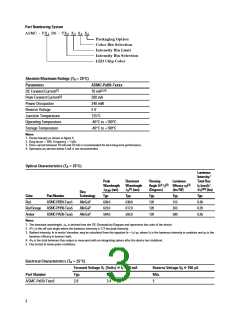
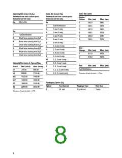
Part Numbering System
ASMC - PX B9 - TX
X
X
X
4 5
1
2
3
Packaging Option
Color Bin Selection
Intensity Bin Limit
Intensity Bin Selection
LED Chip Color
Absolute Maximum Ratings (TA = 25°C)
Parameters
ASMC-PxB9-Txxxx
[3,4]
DC Forward Current[1]
Peak Forward Current[2]
Power Dissipation
70 mA
200 mA
240 mW
Reverse Voltage
5 V
Junction Temperature
Operating Temperature
Storage Temperature
125°C
-40°C to +100°C
-40°C to +100°C
Notes:
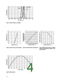
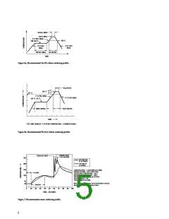
1. Derate linearly as shown in figure 4.
2. Duty factor = 10%, Frequency = 1 kHz.
3. Drive current between 10 mA and 70 mA is recommended for best long-term performance.
4. Operation at currents below 5 mA is not recommended.
Optical Characteristics (TA = 25°C)
Luminous
Intensity/
Total Flux
IV (mcd)/
FV[4,5] (lm)
Peak
Wavelength
Dominant
Wavelength
lD[1] (nm)
Viewing
Luminous
Efficacy hV
(lm/ W)
Angle 2q1/ 2
[2]
[3]
lPEAK (nm)
(Degrees)
Dice
Color
Part Number
Technology
Typ.
Typ.
Typ.
120
120
120
Typ.
155
263
500
Typ.
0.30
0.29
0.26
Red
ASMC-PRB9-Txxx5
ASMC-PHB9-Txxx5
ASMC-PAB9-Txxx5
AlInGaP
AlInGaP
AlInGaP
639.0
623.0
594.0
630.0
617.0
592.0
Red Orange
Amber
Notes:
1. The dominant wavelength, lD, is derived from the CIE Chromaticity Diagram and represents the color of the device.
2. q1/ 2 is the off-axis angle where the luminous intensity is 1/ 2 the peak intensity.
3. Radiant intensity, Ie in watts/ steradian, may be calculated from the equation Ie = IV/ hV, where IV is the luminous intensity in candelas and hV is the
luminous efficacy in lumens/ watt.
4. FV is the total luminous flux output as measured with an integrating sphere after the device has stabilized.
5. Flux tested at mono pulse conditions.
Electrical Characteristics (TA = 25°C)
Forward Voltage V (Volts) @ IF = 50 mA
Reverse Voltage V @ 100 µA
F
R
Part Number
Typ.
Max.
Min.
ASMC-PxB9-Txxx5
2.8
3.4
5
3

 AGILENT [ AGILENT TECHNOLOGIES, LTD. ]