AMS1117
APPLICATION HINTS
The AMS1117 series of adjustable and fixed regulators are easy to
use and are protected against short circuit and thermal overloads.
Thermal protection circuitry will shut-down the regulator should
the junction temperature exceed 165°C at the sense point.
Pin compatible with older three terminal adjustable regulators,
these devices offer the advantage of a lower dropout voltage, more
precise reference tolerance and improved reference stability with
temperature.
D1
AMS1117
VOUT
VIN
IN
OUT
ADJ
+
COUT
R1
2
2µF
Stability
CADFJ
R2
10
µ
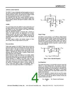
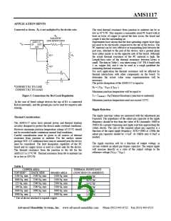
The circuit design used in the AMS1117 series requires the use of
an output capacitor as part of the device frequency compensation.
The addition of 22µF solid tantalum on the output will ensure
stability for all operating conditions.
Figure 1.
When the adjustment terminal is bypassed with a capacitor to
improve the ripple rejection, the requirement for an output
capacitor increases. The value of 22µF tantalum covers all cases
of bypassing the adjustment terminal. Without bypassing the
adjustment terminal smaller capacitors can be used with equally
good results.
Output Voltage
The AMS1117 series develops a 1.25V reference voltage between
the output and the adjust terminal. Placing a resistor between these
two terminals causes a constant current to flow through R1 and
down through R2 to set the overall output voltage. This current is
normally the specified minimum load current of 10mA. Because
IADJ is very small and constant it represents a small error and it
can usually be ignored.
To further improve stability and transient response of these
devices larger values of output capacitor can be used.
Protection Diodes
Unlike older regulators, the AMS1117 family does not need any
protection diodes between the adjustment pin and the output and
from the output to the input to prevent over-stressing the die.
Internal resistors are limiting the internal current paths on the
AMS1117 adjustment pin, therefore even with capacitors on the
adjustment pin no protection diode is needed to ensure device
safety under short-circuit conditions.
AMS1117
VOUT
VIN
IN
OUT
ADJ
VREF
R1
R2
IADJ
50µA
Diodes between the input and output are not usually needed.
Microsecond surge currents of 50A to 100A can be handled by the
internal diode between the input and output pins of the device. In
normal operations it is difficult to get those values of surge
currents even with the use of large output capacitances. If high
value output capacitors are used, such as 1000µF to 5000µF and
the input pin is instantaneously shorted to ground, damage can
occur. A diode from output to input is recommended, when a
crowbar circuit at the input of the AMS1117 is used (Figure 1).
VOUT = VREF (1+ R2/R1)+IADJR2
Figure 2. Basic Adjustable Regulator
Load Regulation
True remote load sensing it is not possible to provide, because the
AMS1117 is a three terminal device. The resistance of the wire
connecting the regulator to the load will limit the load regulation.
The data sheet specification for load regulation is measured at the
bottom of the package. Negative side sensing is a true Kelvin
connection, with the bottom of the output divider returned to the
negative side of the load.
The best load regulation is obtained when the top of the resistor
divider R1 is connected directly to the case not to the load. If R1
were connected to the load, the effective resistance between the
regulator and the load would be:
RP x ( R2+R1 ) , RP = Parasitic Line Resistance
R1
Advanced Monolithic Systems, Inc. www.advanced-monolithic.com Phone (925) 443-0722 Fax (925) 443-0723

 ADMOS [ ADVANCED MONOLITHIC SYSTEMS ]