ADSemiconductor®
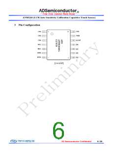
ANMG04 (4-CH Auto Sensitivity Calibration Capacitive Touch Sensor)
7 Electrical Characteristics
▪ VDD=3.3V, Typical system frequency (Unless otherwise noted), TA = 25℃
Characteristics
Symbol
Test Condition
Min
Typ
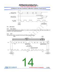
Max
Units
Power supply requirement and current consumption
Operating voltage
VDD
IDD
2.5
-
5.5
-
V
Current consumption
VDD= 3.3V, Standby state
0.50
2.1
mA
Reset and input level
Internal reset voltage
Input high level
VDD_RST
VIH
TA = 25℃
-
-
V
V
V
| IIH | ≤ +5μA
| IIL | ≤ +5μA
VDD*0.6
–0.3
VDD+0.3
VDD*0.3
Input low level
VIL
Slow calibration speed
Normal calibration speed
Fast calibration speed
-
-
-
100
80
60
-
-
-
Self calibration time after
system reset
TCAL
RP/U
msec
Internal Pull Up resister of
SDA, SCL, INT
-
30
-
kΩ
Touch sensing performance
Minimum detective
capacitance difference
Sense input
ΔCMIN
CS
0.1
-
-
-
-
pF
pF
Ω
50
capacitance range1
Output impedance
(open drain)
ΔC > ΔCMIN
ΔC < ΔCMIN
-
-
12
30M
-
-
Zo
System performance
Max. output current
(LED drive current)
IOUT
Per unit drive output port
-
-
8.0
㎃
LED PWM control2
NPWM
-
-
-
-
16
256
-
-
-
step
step
MHz
sec
Sensitivity control3
Max. I2C SCL clock speed
Touch expired time
fSCL_MAX
TEX
Maximum internal I2C clock
Normal calibration speed
2
-
30
1
The sensitivity can be decreased with higher parallel capacitance of CS pin including parasitic capacitance made by
neighbor GND or other pattern. The series resistor(under 1kΩ) of CS can be used in noisy condition to avoid mal-function
from external surge and ESD.
2
Refer to the chapter 10.2.12. LED luminance control register
3
Refer to the chapter 10.2.8. Sensitivity register
AD Semiconductor Confidential
10 / 29

 ADI [ ADI ]