Data Sheet
ADM3055E/ADM3057E
Surface Tracking
Calculation and Use of Parameters Example
Surface tracking is addressed in electrical safety standards by
setting a minimum surface creepage based on the working
voltage, the environmental conditions, and the properties of the
insulation material. Safety agencies perform characterization
testing on the surface insulation of components, allowing the
components to be categorized in different material groups.
Lower material group ratings are more resistant to surface
tracking and can therefore provide adequate lifetime with
smaller creepage. The minimum creepage for a given working
voltage and material group is in each system level standard and
is based on the total rms voltage across the isolation, pollution
degree, and material group. See Table 3 for the material group
and creepage information for the ADM3055E and the ADM3057E
isolated CAN transceivers.
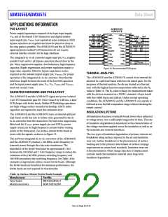
The following example frequently arises in power conversion
applications. Assume that the line voltage on one side of the
isolation is 240 VAC RMS, and a 400 VDC bus voltage is present on
the other side of the isolation barrier. The isolator material is
polyimide. To establish the critical voltages used to determine
the creepage, clearance, and lifetime of a device, see Figure 34
and the equations that follow.
V
AC RMS
V
V
V
DC
PEAK
RMS
Insulation Wear Out
The lifetime of insulation caused by wear out is determined by
the thickness, material properties, and the voltage stress applied
across the insulation. It is important to verify that the product
lifetime is adequate at the application working voltage. The
working voltage supported by an isolator for wear out may not
be the same as the working voltage supported for tracking. The
working voltage applicable to tracking is specified in most
standards.
TIME
Figure 34. Critical Voltage Example
The working voltage across the barrier from Equation 1 is
2
VRMS = VAC
2 +VDC
RMS
VRMS = 2402 + 4002
RMS = 466 V
Testing and modeling show that the primary driver of long-term
degradation is displacement current in the polyimide insulation,
causing incremental damage. The stress on the insulation can be
divided into broad categories, such as dc stress and ac component,
time varying voltage stress. DC stress causes little wear out because
there is no displacement current, whereas ac component, time
varying voltage stress causes wear out.
V
Use this VRMS value as the working voltage in conjunction with
the material group and pollution degree to determine the
creepage required by a system standard.
To determine if the lifetime is adequate, obtain the time varying
portion of the working voltage. To obtain the ac rms voltage,
use Equation 2.
The ratings in certification documents are typically based on
60 Hz sinusoidal stress to reflect isolation from the line voltage.
However, many practical applications have combinations of 60 Hz
ac and dc across the barrier, as shown in Equation 1. Because
only the ac portion of the stress causes wear out, the equation
can be rearranged to solve for the ac rms voltage, as shown in
Equation 2. For insulation wear out with the polyimide materials
used in these products, the ac rms voltage determines the
product lifetime.
2
VAC
VAC
= VRMS2 −VDC
RMS
=
4662 − 4002
RMS
VAC RMS = 240 VRMS
In this case, the ac rms voltage is simply the line voltage of
240 VRMS. This calculation is more relevant when the waveform is
not sinusoidal. The calculated ac rms voltage is compared to the
limits for the working voltage in Table 11 for the expected
lifetime of the device, which is less than a 60 Hz sine wave, and
is well within the limit for a 50-year service life.
2
VRMS = VAC
2 +VDC
(1)
RMS
or
2
VAC
= VRMS2 −VDC
(2)
RMS
The dc working voltage limit is set by the creepage of the
package as specified in IEC 60664-1. This value can differ for
specific system level standards.
where:
V
V
V
RMS is the total rms working voltage.
AC RMS is the time varying portion of the working voltage.
DC is the dc offset of the working voltage.
Rev. A | Page 23 of 24

 ADI [ ADI ]