ADM1026
Fan Speed Control Outputs
•
Writing to the EEPROM should be restricted because its
typical cycle life is 100,000 write operations, due to the
usual EEPROM wear-out mechanisms.
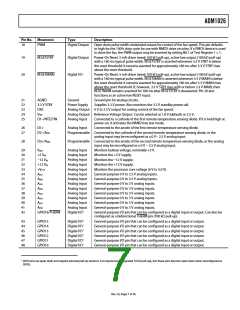
The ADM1026 has two outputs intended to control fan speed,
though they can also be used for other purposes. Pin 18 is an
open drain, pulse width modulated (PWM) output with a
programmable duty cycle and an output frequency of 75 Hz.
Pin 23 is connected to the output of an on-chip, 8-bit, digital-to-
analog converter with an output range of 0 V to 2.5 V.
The EEPROM in the ADM1026 has been qualified for two key
EEPROM memory characteristics: memory cycling endurance
and memory data retention.
Endurance qualifies the ability of the EEPROM to be cycled
through many program, read, and erase cycles. In real terms,
a single endurance cycle is composed of four independent,
sequential events, as follows:
Either or both of these outputs may be used to implement a
temperature-controlled fan by controlling the speed of a fan
using the temperature measured by the on-chip temperature
sensor or remote temperature sensors.
1. Initial page erase sequence
2. Read/verify sequence
3. Program sequence
INTERNAL REGISTERS
Table 4 describes the principal registers of the ADM1026. For
more detailed information, see Table 11 to Table 124.
4. Second read/verify sequence
In reliability qualification, every byte is cycled from 00h to FFh
until a first fail is recorded, signifying the endurance limit of the
EEPROM memory.
Table 4. Principal Registers
Type
Description
Address Pointer
Contains the address that selects one of
the other internal registers. When writing
to the ADM±026, the first byte of data is
always a register address, and is written
to the address pointer register.
Provide control and configuration for
various operating parameters.
Contain counter prescaler values for fan
speed measurement.
Contain speed values for PWM and DAC
fan drive outputs.
Configure the GPIO pins as input or
output and for signal polarity.
Store the results of analog voltage inputs,
temperature, and fan speed
measurements, along with their limit
values.
Store events from the various interrupt
sources.
Retention quantifies the ability of the memory to retain its
programmed data over time. The EEPROM in the ADM1026
has been qualified in accordance with the formal JEDEC
Retention Lifetime Specification (A117) at a specific junction
temperature (TJ = 55°C) to guarantee a minimum of 10 years
retention time. As part of this qualification procedure, the
EEPROM memory is cycled to its specified endurance limit
described above before data retention is characterized. This
means that the EEPROM memory is guaranteed to retain its
data for its full specified retention lifetime every time the
EEPROM is reprogrammed. Note that retention lifetime based
on an activation energy of 0.6 V derates with TJ, as shown in
Figure 16.
Configuration
Registers
Fan Divisor
Registers
DAC/PWM
Control Registers
GPIO Configuration
Registers
Value and Limit
Registers
300
250
200
150
100
Status Registers
Mask Registers
Allow masking of individual interrupt
sources.
EEPROM
The ADM1026 has 8 kB of nonvolatile, electrically erasable,
programmable read-only memory (EEPROM) from register
Addresses 8000h to 9FFFh. This may be used for permanent
storage of data that is not lost when the ADM1026 is powered
down, unlike the data in the volatile registers. Although referred
to as read-only memory, the EEPROM can be written to (as well
as read from) via the serial bus in exactly the same way as the
other registers. The main differences between the EEPROM and
other registers are
50
0
110
40
50
60
70
80
90
100
120
JUNCTION TEMPERATURE (°C)
Figure 16. Typical EEPROM Memory Retention
•
An EEPROM location must be blank before it can be
written to. If it contains data, it must first be erased.
Writing to EEPROM is slower than writing to RAM.
•
Rev. A | Page ±± of 56

 ADI [ ADI ]