ADM1026
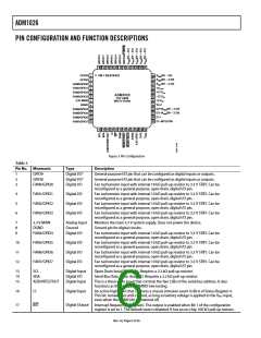
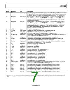
Pin No. Mnemonic
Type
Description
±8
PWM
Digital Output
Open drain pulse width modulated output for control of the fan speed. This pin defaults
to high for the ±00% duty cycle for use with NMOS drive circuitry. If a PMOS device is used
to drive the fan, the PWM output may be inverted by setting Bit ± of Test Register ± = ±.
±9
RESETSTBY
Digital Output
Digital I/O
Power-On Reset. 5 mA driver (weak ±00 kΩ pull-up), active low output (±00 kΩ pull-up)
with a ±80 ms typical pulse width. RESETSTBY is asserted whenever 3.3 V STBY is below
the reset threshold. It remains asserted for approximately ±80 ms after 3.3 V STBY rises
above the reset threshold.
Power-On Reset. 5 mA driver (weak ±00 kΩ pull-up), active low output (±00 kΩ pull-up)
with a ±80 ms typical pulse width. RESETMAIN is asserted whenever 3.3 V MAIN is below
the reset threshold. It remains asserted for approximately ±80 ms after 3.3 V MAIN rises
above the reset threshold. If, however, 3.3 V STBY rises with or before 3.3 V MAIN, then
RESETMAIN remains asserted for ±80 ms after RESETSTBY is deasserted. Pin 20 also
functions as an active low RESET input.
20
RESETMAIN
2±
22
23
24
25
AGND
3.3 V STBY
DAC
VREF
D±–/NTESTIN
Ground
Power Supply
Ground pin for analog circuits.
Supplies 3.3 V power. Also monitors the 3.3 V standby power rail.
Analog Output 0 V to 2.5 V output for analog control of the fan speed.
Analog Output Reference Voltage Output. Can be selected as ±.8 V (default) or 2.5 V.
Analog Input
Connected to a cathode of the first remote temperature sensing diode. If it is held high at
power-on, it activates the NAND tree test mode.
26
27
D±+
D2–/AIN9
Analog Input
Connected to the anode of the first remote temperature sensing diode.
Programmable Connected to the cathode of the second remote temperature sensing diode, or the
analog input may be reconfigured as a 0 V− 2.5 V analog input.
28
D2+/AIN8
Programmable Connected to the anode of the second remote temperature sensing diode, or the analog
input may be reconfigured as a 0 V − 2.5 V analog input.
29
30
3±
32
33
34
35
36
37
38
39
40
4±
42
VBAT
Analog Input
Analog Input
Analog Input
Analog Input
Analog Input
Analog Input
Analog Input
Analog Input
Analog Input
Analog Input
Analog Input
Analog Input
Analog Input
Digital I/O±
Monitors battery voltage, nominally +3 V.
Monitors the +5 V supply.
+5 VIN
−±2 VIN
+±2 VIN
+VCCP
AIN7
AIN6
AIN5
AIN4
AIN3
Monitors the −±2 V supply.
Monitors the +±2 V supply.
Monitors the processor core voltage (0 V to 3.0 V).
General-purpose 0 V to 2.5 V analog inputs.
General-purpose 0 V to 2.5 V analog inputs.
General-purpose 0 V to 3 V analog inputs.
General-purpose 0 V to 3 V analog inputs.
General-purpose 0 V to 3 V analog inputs.
General-purpose 0 V to 3 V analog inputs.
General-purpose 0 V to 3 V analog inputs.
General-purpose 0 V to 3 V analog inputs.
AIN2
AIN±
AIN0
GPIO±6/THERM
General-purpose I/O pin that can be configured as a digital input or output. Can also be
configured as a bidirectional THERM pin (±00 kΩ pull-up).
43
44
45
46
47
48
GPIO±5
GPIO±4
GPIO±3
GPIO±2
GPIO±±
GPIO±0
Digital I/O±
Digital I/O±
Digital I/O±
Digital I/O±
Digital I/O±
Digital I/O±
General-purpose I/O pin that can be configured as a digital input or output.
General-purpose I/O pin that can be configured as a digital input or output.
General-purpose I/O pin that can be configured as a digital input or output.
General-purpose I/O pin that can be configured as a digital input or output.
General-purpose I/O pin that can be configured as a digital input or output.
General-purpose I/O pin that can be configured as a digital input or output.
± GPIO pins are open drain and require external pull-up resistors. Fan inputs have integrated ±0 kΩ pull-ups, but these pins become open drain when reconfigured as
GPIOs.
Rev. A | Page 7 of 56

 ADI [ ADI ]