AD8615/AD8616/AD8618
Calculating Power by Measuring Ambient and Case
Temperature
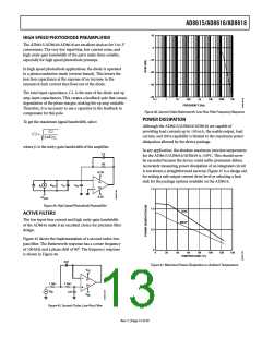
These thermal resistance curves were determined using
the AD8616 thermal resistance data for each package and
a maximum junction temperature of 150°C. The following
formula can be used to calculate the internal junction tem-
perature of the AD8615/AD8616/AD8618 for any application:
The two equations for calculating junction temperature are
TJ = TA + P θJA
where:
TJ = PDISS × θJA + TA
TJ = junction temperature
TA = ambient temperature
where:
θJA = the junction-to-ambient thermal resistance
TJ = junction temperature
PDISS = power dissipation
θJA = package thermal resistance, junction-to-case
TJ = TC + P θJC
TA = ambient temperature of the circuit
where TC is case temperature and θJA and θJC are given in the
data sheet.
To calculate the power dissipated by the AD8615/
AD8616/AD8618, use
The two equations for calculating P (power) are
TA + P θJA = TC + P θJC
PDISS = ILOAD × (VS – VOUT
)
where:
P = (TA – TC)/(θJC – θJA)
ILOAD = output load current
VS = supply voltage
VOUT = output voltage
Once power has been determined, it is necessary to recalculate
the junction temperature to ensure that it has not been
exceeded.
The quantity within the parentheses is the maximum voltage
developed across either output transistor.
The temperature should be measured directly on and near the
package, but not touching it. Measuring the package can be
difficult. A very small bimetallic junction glued to the package
can be used, or an infrared sensing device can be used if the
spot size is small enough.
POWER CALCULATIONS FOR VARYING OR
UNKNOWN LOADS
Often, calculating power dissipated by an integrated circuit to
determine if the device is being operated in a safe range is not
as simple as it might seem. In many cases, power cannot be
directly measured. This may be the result of irregular output
waveforms or varying loads. Indirect methods of measuring
power are required.
Calculating Power by Measuring Supply Current
Power can be calculated directly if the supply voltage and
current are known. However, the supply current can have a dc
component with a pulse directed into a capacitive load, which
could make the rms current very difficult to calculate. This
difficulty can be overcome by lifting the supply pin and
inserting an rms current meter into the circuit. For this method
to work, make sure the current is delivered by the supply pin
being measured. This is usually a good method in a single-
supply system; however, if the system uses dual supplies, both
supplies may need to be monitored.
There are two methods to calculate power dissipated by
an integrated circuit. The first is to measure the package
temperature and the board temperature. The second is
to directly measure the circuits supply current.
Rev. C | Page 14 of 20

 ADI [ ADI ]