AD1819B
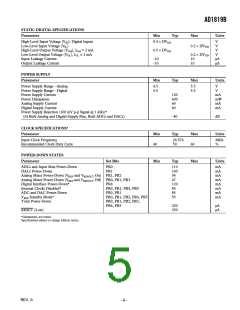
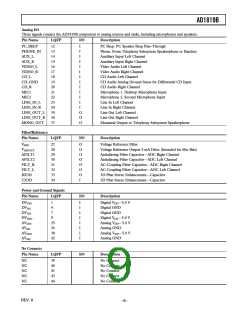
STATIC DIGITAL SPECIFICATIONS
Parameter
Min
Typ
Max
Units
High-Level Input Voltage (VIH): Digital Inputs
Low-Level Input Voltage (VIL)
High-Level Output Voltage (VOH), IOH = 2 mA
Low-Level Output Voltage (VOL), IOL = 2 mA
Input Leakage Current
0.4 × DVDD
V
V
V
V
µA
µA
0.2 × DVDD
0.5 × DVDD
0.2 × DVDD
10
10
–10
–10
Output Leakage Current
POWER SUPPLY
Parameter
Min
Typ
Max
Units
Power Supply Range—Analog
Power Supply Range—Digital
4.5
4.5
5.5
5.5
V
V
Power Supply Current
Power Dissipation
Analog Supply Current
Digital Supply Current
120
600
60
mA
mW
mA
mA
60
Power Supply Rejection (100 mV p-p Signal @ 1 kHz)*
(At Both Analog and Digital Supply Pins, Both ADCs and DACs)
–40
dB
CLOCK SPECIFICATIONS*
Parameter
Min
Typ
Max
Units
Input Clock Frequency
Recommended Clock Duty Cycle
24.576
50
MHz
%
40
60
POWER-DOWN STATES
Parameter
Set Bits
Min
Typ
Max
Units
ADCs and Input Mux Power-Down
DACs Power-Down
Analog Mixer Power-Down (VREF and VREFOUT On) PR1, PR2
Analog Mixer Power-Down (VREF and VREFOUT Off) PR0, PR1, PR3
Digital Interface Power-Down*
Internal Clocks Disabled*
ADC and DAC Power-Down
VREF Standby Mode*
PR0
PR1
110
100
54
47
120
85
mA
mA
mA
mA
mA
mA
mA
mA
PR4
PR0, PR1, PR4, PR5
PR0, PR1
PR0, PR1, PR2, PR4, PR5
PR0, PR1, PR2, PR3,
PR4, PR5
85
55
Total Power-Down
220
250
µA
µA
RESET (Low)
*Guaranteed, not tested.
Specifications subject to change without notice.
REV. 0
–5–

 ADI [ ADI ]