ISD5100 – SERIES
7.5.3. Reading Digital Data
The Digital Read command utilizes the combined I2C command format. That is, a command is sent to
the chip using the write data direction. Then the data direction is reversed by sending a repeated
start condition, and the slave address with R/W set to 1. After this, the slave device (ISD5100-
Series) begins to send data to the master until the master generates a NACK. If the part encounters
an overflow condition, the INT pin is pulled LOW. No other communication with the master is
possible due to the master generating ACK signals.
Digital Write and Digital Read can be done a “block” at a time. Thus, only 64 bits need be read in
each Digital Read command sequence.
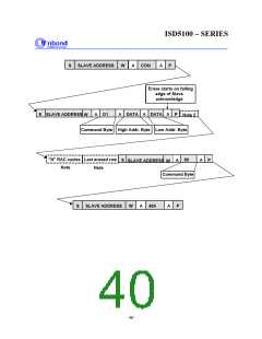
7.5.4. Example Command Sequences
An explanation and graphical representation of the Erase, Write and Read operations are found
below.
Note: All sequences assumes that the chip is in power-down mode before the commands are sent.
7.5.4.1. Erase Digital Data
Erase
=====
I2CStart
SendByte(0x80)
WaitACK
- Write, Slave address zero
WaitSCLHigh
SendByte(0xc0)
WaitACK
- Enter Digital Mode Command
WaitSCLHigh
I2CStop
I2CStart
SendByte(0x80)
WaitACK
WaitSCLHigh
SendByte(0xd1)
WaitACK
- Write, Slave address zero
- Digital Erase Command
WaitSCLHigh
SendByte(row/256) - high address byte
Publication Release Date: October, 2003
Revision 0.2
- 37 -

 WINBOND [ WINBOND ]