ISD1600 SERIES
6. PIN DESCRIPTION
PIN NAME
SOIC / PDIP
FUNCTIONS
PIN NO.
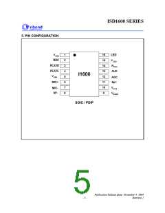
VSSD, VSSA
,
1, 5, 9
Ground: VSSD is the ground for digital circuits. VSSA is the
ground for analog circuits, whereas VSSAD is the ground for
PWM speaker driver. They should be separate ground paths
connecting to ground of power supply to minimize noises.
VSSAD
REC [1]
PLAYE [1]
PLAYL [1]
MIC+
2
3
4
6
Record: The device starts recording whenever REC transits
from HIGH to LOW and stays at LOW. Recording stops
when the signal returns to HIGH. This pin has an internal
pull-up device[2].
Edge-trigger Playback: A playback operation starts when
this input detects a LOW going signal exceeding the
specified debounced time. This pin has an internal pull-up
device[2].
Level-trigger Playback: A playback operation begins when
this input detects a LOW going signal and remains at LOW.
Playback stops when the signal returns to HIGH. This pin
has an internal pull-up device[2].
Microphone Positive Input: The input transfers the signals
to the preamplifier. The internal Automatic Gain Control
(AGC) circuit controls the gain of the preamplifier. An
external microphone should be AC coupled to this pin via a
series capacitor. The capacitor value, together with an
internal 10 KΩ resistance on this pin, determines the low-
frequency cutoff for the ISD1600 passband.
MIC-
SP-
7
8
Microphone Negative Input: This is the inverting input to
the microphone preamplifier. It provides input noise-
cancellation, or common-mode rejection, when the
microphone is connected differentially to the device.
Speaker Negative : The SP-, Class D PWM output, provide
a differential output with SP+ pin to drive 8ꢀ speaker or
buzzer. During power down or recording, this pin is tri-
stated.
VCCA, VCCD
10, 15
Supply Voltages: Internal analog and digital circuits use
separate power busses to minimize noises inside the chip.
These power busses are brought out to separate pads and
should be tied together as close to the power supply as
possible. It is important that the power supplies are
decoupled as close as possible to the device.
SP+
11
Speaker Positive : The SP+, Class D PWM output, provide
a differential output with SP- pin to drive an 8ꢀ speaker or
buzzer directly. During power down or recording, this pin is
tri-stated.
- 6 -

 WINBOND [ WINBOND ]