HV300
___________________________________________________________________________________________
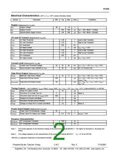
Electrical Characteristics (-40°C ! TA ! +85°C unless otherwise noted)
Symbol
Parameter
Min
-90
Typ
Max
Units
Conditions
Supply (Referenced to VDD pin)
VEE
Supply Voltage
-10
650
400
V
IEE
Supply Current
550
330
VEE = -48V, Mode = Limiting
VEE = -48V, Mode = Standby
µA
µA
IEE
Standby Mode Supply Current
OV and UV Control (Referenced to VEE pin)
VUVH
VUVL
VUVH
IUV
UV High Threshold
UV Low Threshold
UV Hysteresis
1.26
1.16
100
V
V
Low to High Transition
High to Low Transition
mV
nA
V
UV Input Current
OV High Threshold
OV Low Threshold
OV Hysteresis
1
VUV = VEE + 1.9V
VOVH
VOVL
VOVH
IOV
1.26
1.16
100
Low to High Transition
High to Low Transition
V
mV
nA
OV Input Current
1
VOV = VEE + 0.5V
Current Limit (Referenced to VEE pin)
VSENSE
Current Limit Threshold Voltage
40
50
50
60
mV VUV = VEE + 1.9V, VOV = VEE + 0.5V
RSENSE
Sense Resistor Value (SENSE to VEE
)
For 1A Current Limit
mΩ
Gate Drive Output (Referenced to VEE pin)
VGATE
Maximum Gate Drive Voltage
9
10
11
V
VUV = VEE + 1.9V, VOV = VEE + 0.5V
IGATEUP
Gate Drive Pull-Up Current
500
V
UV = VEE + 1.9V, VOV = VEE + 0.5V,
µA
VGATE = VEE
IGATEDOWN Gate Drive Pull-Down Current
40
mA VUV = VEE, VOV = VEE + 0.5V, VGATE
VEE + 4V
=
Timing Control - Test Conditions: CLOAD=100µF, CRAMP=10nF, VUV = VEE + 1.9V, VOV = VEE + 0.5V, External MOSFET is IRF530*
IRAMP
Ramp Pin Output Current
10
µA
tPOR
Time from UV to Gate Turn On
2
ms (Note 1)
tRISE
Time from Gate Turn On to VSENSE Limit
Duration of Current Limit Mode
400
µs
ms
ms
tLIMIT
<5
5
tPWRGD
VRAMP
Time from Current Limit to PWRGD
Voltage on Ramp Pin in Current Limit Mode
3.6
V
(Note 2)
Power Good Output (Referenced to VEE pin)
VPWRGD
Power Good Pin Breakdown Voltage
90
V
V
VPWRGD
Power Good Pin Output Low Voltage
0.5
0.8
IPWRGD = 1mA
Dynamic Characteristics
tGATEHLOV
OV Comparator Transition
<500
<500
ns
ns
tGATEHLUV
UV Comparator Transition
Note 1: This timing depends on the threshold voltage of the external N-Channel MOSFET. The higher its threshold is, the longer this
timing.
Note 2: This voltage depends on the characteristics of the external N-Channel MOSFET. Vto = 3V for an IRF530.
*IRF530 is a registered trademark of International Rectifier.
Prepared by the Telecom Group
2 of 5
Rev. E
7/19/2001
_________________________________________________________________ ______________________________________________
Supertex, Inc. 1235 Bordeaux Drive, Sunnyvale, CA 94089 TEL: (408) 744-0100 FAX: (408) 222-4895 www.supertex.com

 SUPERTEX [ Supertex, Inc ]