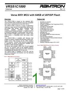
VRS51C1000
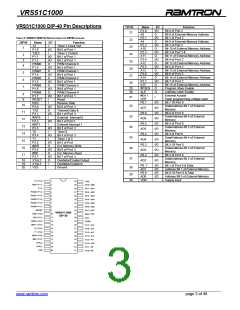
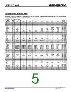
VRS51C1000 DIP-40 Pin Descriptions
DIP40
21
Name
P2.0
A8
P2.1
A9
P2.2
A10
P2.3
A11
P2.4
A12
P2.5
A13
P2.6
A14
P2.7
A15
I/O
I/O
O
I/O
O
I/O
O
I/O
O
I/O
O
I/O
O
I/O
O
Function
Bit 0 of Port 2
Bit 8 of External Memory Address
Bit 1 of Port 2
Bit 9 of External Memory Address
Bit 2 of Port 2
Bit 10 of External Memory Address
Bit 3 of Port 2 &
Bit 11 of External Memory Address
Bit 4 of Port 2
Bit 12 of External Memory Address
Bit 5 of Port 2
Bit 13 of External Memory Address
Bit 6 of Port 2
Bit 14 of External Memory Address
Bit 7 of Port 2
Bit 15 of External Memory Address
Program Store Enable
Address Latch Enable
External Access
Flash programming voltage input
Bit 7 Of Port 0
Data/Address Bit 7 of External
Memory
Bit 6 of Port 0
Data/Address Bit 6 of External
Memory
Bit 5 of Port 0
Data/Address Bit 5 of External
Memory
Bit 4 of Port 0
Data/Address Bit 4 of External
Memory
Bit 3 Of Port 0
Data/Address Bit 3 of External
Memory
Bit 2 of Port 0
Data/Address Bit 2 of External
Memory
Bit 1 of Port 0 & Data
Address Bit 1 of External Memory
Bit 0 Of Port 0 & Data
Address Bit 0 of External Memory
Supply input
TABLE 2: VRS51C1000 PIN DESCRIPTIONS FOR DIP40 PACKAGE
22
23
24
25
26
27
28
DIP40
Name
T2
P1.0
T2EX
P1.1
P1.2
PWM0
P1.3
PWM1
P1.4
PWM2
P1.5
PWM3
P1.6
PWM4
P1.7
RESET
RXD
P3.0
TXD
P3.1
#INT0
P3.2
#INT1
P3.3
I/O
I
Function
Timer 2 Clock Out
1
I/O
I
I/O
I/O
O
I/O
O
I/O
O
I/O
O
I/O
O
I/O
I
I
I/O
O
I/O
I
I/O
I
I/O
I
I/O
I
I/O
O
I/O
O
I/O
O
Bit 0 of Port 1
Timer 2 Control
Bit 1 of Port 1
Bit 2 of Port 1
PWM Channel 0
Bit 3 of Port 1
PWM Channel 1
Bit 4 of Port 1
PWM Channel 2
Bit 5 of Port 1
PWM Channel 3
Bit 6 of Port 1
PWM Channel 4
Bit 7 of Port 1
Reset
Receive Data
Bit 0 of Port 3
Transmit Data &
Bit 1 of Port 3
External Interrupt 0
Bit 2 of Port 3
External Interrupt 1
Bit 3 of Port 3
Timer 0
Bit 4 of Port 3
Timer 1 & 3
Bit 5 of Port
Ext. Memory Write
Bit 6 of Port 3
Ext. Memory Read
Bit 7 of Port 3
Oscillator/Crystal Output
Oscillator/Crystal In
Ground
2
3
4
5
6
7
I/O
O
O
29
30
#PSEN
ALE
#EA /
VPP
P0.7
O
8
9
31
I
I/O
I/O
I/O
I/O
I/O
I/O
I/O
I/O
I/O
I/O
I/O
I/O
10
32
AD7
P0.6
AD6
P0.5
AD5
P0.4
AD4
P0.3
AD3
P0.2
AD2
11
12
13
14
15
16
17
33
34
35
36
T0
P3.4
T1
P3.5
#WR
P3.6
#RD
P3.7
37
38
18
19
20
XTAL2
XTAL1
VSS
I
-
P0. 1
AD1
P0.0
AD0
VDD
I/O
I/O
I/O
I/O
-
39
40
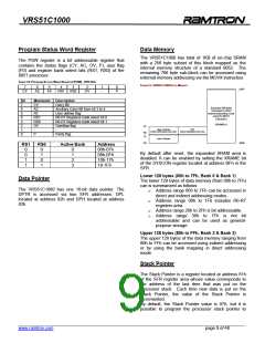
T2 / P1.0
T2EX / P1.1
P1.2
1
2
3
4
5
6
7
8
9
40
39
38
37
36
35
34
33
32
31
30
29
28
27
26
25
24
23
22
21
VDD
P0.0 / AD0
P0.1 / AD1
P0.2 / AD2
P0.3 / AD3
P0.4 / AD4
P0.5 / AD5
P0.6 / AD6
P0.7 / AD7
#EA / VPP
ALE
PWM0 / P1.3
PWM1 / P1.4
PWM2 / P1.5
PWM3 / P1.6
PWM4 / P1.7
RESET
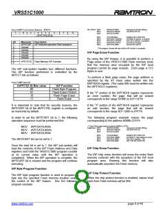
VRS51C1000
DIP-40
RXD / P3.0
TXD / P3.1
#INT0 / P3.2
#INT1 / P3.3
T0 / P3.4
10
11
12
13
14
15
16
17
18
19
20
PSEN
P2.7 / A15
P2.6 / A14
P2.5 / A13
P2.4 / A12
P2.3 / A11
P2.2 / A10
P2.1 / A9
P2.0 / A8
T1 / P3.5
#WR / P3.6
#RD / P3.7
XTAL2
XTAL1
VSS
______________________________________________________________________________________________
www.ramtron.com page 3 of 48

 RAMTRON [ RAMTRON INTERNATIONAL CORPORATION ]