AMIS-52150 Low-Power Transceiver with Clock and Data Recovery
Data Sheet
Table 15: Internal I2C Pull-up Resistors
Pin
Function
Internal Pull-up R
Internal Pull-up R
Typ.
15
15
Units
KΩ
KΩ
I2CDATA
I2 CCLK
Table 16: I2C Bus Device Addressing
Device
AMIS-52150
AMIS-52150
Address (Bin)
01101000
01101001
HEX
68
69
Function
Device write
Device read
Table 17: I2C Control Register
I2C Control Register
Register (HEX)
0x0c
Name
Bits
2
States Comments
I2C address
increment
0
1
Increment after write
Do not increment
The I2CDATA and I2CCLK lines are also used to signal an external controller about internal AMIS-52150 activities such as wakeup. The
receiver can be woken by energy detection during a Sniff operation. The AMIS-52150 can set the application wakeup timer to wake it
from time to time to alert an external controller to perform tasks as defined by the application. The I2CDATA and I2CCLK lines are used
to inform the external controller as to what event woke the AMIS-52150. These functions, Sniff Mode and application wakeup, are
discussed later in this document.
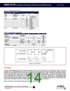
8.10 TX/RX, Data Input/Output
The transmit/receive (TX/RX) pin function can be programmed to be an input for RF transmissions, an output for RF reception, the RC
oscillator signal output, or the recovered data output from the CDR circuits.
In transmit mode, this pin is the digital data input to the AMIS-52150 RF transmit circuit. The data turns the transmit output power
amplifier (PA) on or off. The AMIS-52150 does not perform any protocol conversion on the data bit stream, it is simply a serial bit
stream. The state of the TX/RX pin either turns the output amplifier on, outputting RF signal. Or turns the output amplifier off, no RF
signal output. The TX/RX input can be inverted which causes the state control of the RF output amplifier to be inverted also.
In receive mode, this pin is the digital data output from the AMIS-52150 receivers. The received data is recovered as a high/low (digital
ones and zeros) serial bit stream, the AMIS-52150 does not modify the received data protocol. The receiver is just a pass through
function. The data output state due to the presence of energy in the receiver can be programmed to be either a high level or a low level
at the TX/RX pin. An external controller is needed to decode the information in the recovered data bit stream.
When programmed to be an oscillator output, the TX/RX pin outputs the signal from the RC oscillator. This signal can be used to
monitor the frequency of the RC oscillator to trim the frequency to the desired value.
The TX/RX pin can be programmed to output the recovered data obtained from the clock and data recovery circuits. The AMIS-52150
must be programmed into the CDR mode for this. More information on CDR is found in a later section on CDR.
The functions of the TX/RX port are controlled by writing to the registers shown in Table 18 of the AMIS-52150.
Table 18: TX/RX Pin Definition Control Registers
Register (HEX)
0x0e
Name
RC OSC on TX/RX
Bits
2
States
Comments
RX/TX normal
RC OSC output
Normal levels
Inverted
0
1
0
1
0x1e
TX/RX invert
5
AMI Semiconductor – Rev 4.0, Oct. 06 – M-20535-004
10
www.amis.com

 ONSEMI [ ONSEMI ]