EM73P461A
4-BIT MICRO-CONTROLLER FOR LCD PRODUCT
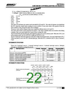
Interrupt controller:
IL0-IL5
: Interrupt latch. Hold all interrupt requests from all interrupt sources. ILr can not be
set by program, but can be reset by program or system reset, so IL only can decide
which interrupt source can be accepted.
MASK0-MASK3 : Except INT0, MASK register can promit or inhibit all interrupt sources.
EI
: Enable interrupt Flip-Flop can promit or inhibit all interrupt sources, when inter-
rupt happened, EI is cleared to "0" automatically, after RTI instruction happened,
EI will be set to "1" again.
Priority checker
: Check interrupt priority when multiple interrupts happened.
INTERRUPT FUNCTION
The procedure of interrupt operation:
1. Push PC and all flags to stack.
2. Set interrupt entry address into PC.
3. Set SF= 1.
4. Clear EI to inhibit other interrupts happened.
5. Clear the IL for which interrupt source has already be accepted.
6. To excute interrupt subroutine from the interrupt entry address.
7. CPU accept RTI, restore PC and flags from stack. Set EI to accept other interrupt requests.
PROGRAM EXAMPLE: To enable interrupt of "INT0, TRGA"
LDIA #1100B;
EXAE; set mask register "1100B"
EICIL 111111B ; enable interrupt F.F.
LCD DRIVER
EM73P461A can directly drive the liquid crystal display (LCD) and has 32 segment, 4 common output pins (1/
2 bias, 1/3 bias). There are total 32x4 dots can be display. The V1, V2, V3, VA, VB, VDD and VSS pins are
the LCD bias generator.
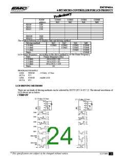
CONTROL OF LCD DRIVER
The LCD driver control command register is P27. When LDC is 0, the LCD is disabled, the COM and SEG
pins are VSS. When LDC is 1, the LCD driver enables.
When the CPU is reseted or during the STOP operation mode, the LCD driver is disabled.
Port27
2
1
0
Initial value : 0000
LDC
DUTY
LDC
0
1
LCD display control
LCD display disable
LCD display enable
DUTY
0 0 0
0 0 1
0 1 0
0 1 1
1 0 0
1 0 1
1 1 *
Driving method select
1/4 duty (1/3 bias)
1/4 duty (1/2 bias)
1/3 duty (1/3 bias)
1/3 duty (1/2 bias)
1/2 duty (1/2 bias)
Static
Reserved
The LCD display data is stored in the display data area of the data memory (RAM).
The display data area begins with address 20H during reset. The LCD display data area ia as below :
* This specification are subject to be changed without notice.
12.27.2001
23

 ELAN [ ELAN MICROELECTRONICS CORP ]