EM73P362
4-BIT MICRO-CONTROLLER FOR LCD PRODUCT
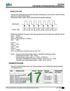
TIMER FUNCTION
For timer mode, timerA increase one at any rising edge of internal pulse. User can choose 4 kinds of internal
pulse rate by setting IPSA for timerA.
When timerA counts overflow, TRGA will be generated to interrupt control unit.
Internal pulse
n
n+1
n+2
n+3
n+4
n+5
n+6
n+7
TimerA value
PROGRAM EXAMPLE: To generate TRGA interrupt request after 60 ms with system clock XlN=32K Hz
LDIA
#0100B;
EXAE; enable mask 2
EICIL 110111B; interrupt latch ←0, enable EI
LDIA
#04H;
STATAL;
LDIA
STATAM;
LDIA
#0CH;
#0FH;
STATAH;
LDIA
#1000B;
OUTA P28; enable timerA with internal pulse rate: XIN/25 Hz
NOTE: The preset value of timer/counter register is calculated as following procedure.
Internal pulse rate: XIN/25 ; XIN = 32KHz
The time of timer counter count one = 25 /XIN = 32/32K=1ms
The number of internal pulse to get timer overflow = 60 ms/ 1ms = 60 = 03CH
The preset value of timer/counter register = 1000H - 03CH = 0FC4H
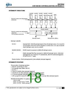
INTERRUPT FUNCTION
There are 3 internal interrupt sources and 2 external interrupt sources. Multiple interrupts are admitted
according the priority.
Type
Interrupt source
Priority Interrupt
Latch
Interrupt
Enable condition
Program ROM
entry address
External Externalinterrupt(INT0)
Internal Reserved
Internal TimerAoverflowinterrupt(TRGA)
Internal TimerBoverflowinterrupt(TRGB)
Internal Time base interrupt(TBI)
External Externalinterrupt(INT1)
1
2
3
4
5
6
IL5
IL4
IL3
IL2
IL1
IL0
EI=1
002H
004H
006H
008H
00AH
00CH
EI=1,MASK3=1
EI=1,MASK2=1
EI=1,MASK1=1
EI=1,MASK0=1
* This specification are subject to be changed without notice.
11.1.2001
17

 ELAN [ ELAN MICROELECTRONICS CORP ]