EM73P361A
4-BIT MICRO-CONTROLLER FOR LCD PRODUCT
PROGRAM EXAMPLE
To enable WDT with 3 x 213/fc detection ftime.
LDIA #0000B
OUTA P21; set WDT detection time and clear WDT counter
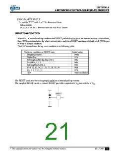
RESETTING FUNCTION
When CPU in normal working condition and RESET pin holds in low level for three instruction cycles at least,
then CPU begins to initialize the whole internal states, and when RESET pin changes to high level, CPU begins
to work in normal condition.
The CPU internal state during reset condition is as following table :
Hardware condition in RESET state
Program counter
Initial value
000h
Status flag
01h
Interrupt enable flip-flop ( EI )
MASK0 ,1, 2, 3
00h
00h
Interrupt latch ( IL )
P10, 11, 12, 16, 21, 25, 27, 28, 29, 30
P4, 5, 6, 7, 23, 24
00h
00h
0Fh
XIN
Start oscillation
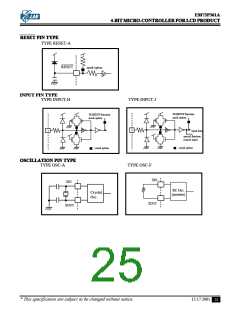
The RESET pin is a hysteresis input pin and it has a internal pull-up resistor.
The simplest RESET circuit is connect RESET pin with a capacitor to VSS and a diode to VDD.
RESET
* This specification are subject to be changed without notice.
12.17.2001
21

 ELAN [ ELAN MICROELECTRONICS CORP ]