EM73P361A
4-BIT MICRO-CONTROLLER FOR LCD PRODUCT
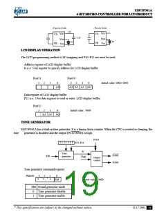
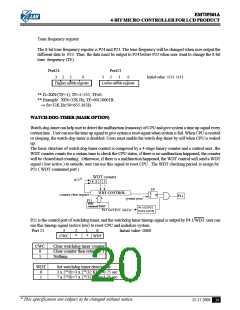
Tone frequency register
The 8-bit tone frequency register is P24 and P23. The tone frequency will be changed when user output the
different data to P23. Thus, the data must be output to P24 before P23 when user want to change the 8-bit
tone frequency (TF).
Port24
3
Port23
2
1
0
3
2
1
0
Initial value : 1111 1111
Higher nibble register
Lower nibble register
** f1=XIN/(TF+1), TF=1~255, TF≠0
** Example : XIN=32K Hz, TF=00110001B.
fo=32K Hz/50=655.36 Hz
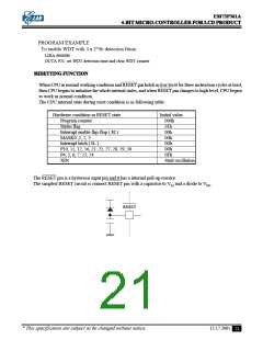
WATCH-DOG-TIMER (MASK OPTION)
Watch-dog-timer can help user to detect the malfunction (runaway) of CPU and give system a time up signal every
certain time . User can use the time up signal to give system a reset signal when system is fail. When CPU is reseted
or sleeping, the watch-dog-timer is disabled. Users must enable the watch-dog-timer by self when CPU is waked
up.
The basic structure of watch-dog-timer control is composed by a 4-stage binary counter and a control unit . the
WDT counter counts for a certain time to check the CPU status, if there is no malfunction happened, the counter
will be cleared and counting . Otherwise, if there is a malfunction happened, the WDT control will send a WDT
signal ( low active ) to outside, user can use this signal to reset CPU . The WDT checking period is assign by
P21 ( WDT command port )
WDT counter
fc/213
0
1 2 3
F/F
WDT CONTROL
R
S
counter clear request
P21
Q
P4.1
system reset
WDT
command PORT
P4.1 OUTPUT
DATA LATCH
P4.1 OUTPUT DATA
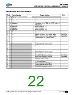
P21 is the control port of watchdog timer, and the watchdog timer timeup signal is output by P4.1/WDT, user can
use this timeup signal (active low) to reset CPU and initialize system.
Port 21
3
2
*
1
*
0
Initial value :0000
CWC
WDT
CWC
0
1
Clear watchdog timer counter
Clear counter then return to 1
Nothing
WDT
0
1
Set watchdog timer detect time
3 x 213/fc=3 x 213/32 KHz=0.75 sec
7 x 213/fc=7 x 213/32K Hz=1.75 sec
* This specification are subject to be changed without notice.
12.17.2001
20

 ELAN [ ELAN MICROELECTRONICS CORP ]