VS1005g Datasheet
10 VS1005 PERIPHERALS AND REGISTERS
10.16 Line and Mic Inputs
VS1005 has three 24-bit AD input channels and an FM receiver. ADs 1 and 2 can be configured
for mic or line input mode (stereo AD). AD 3 can only be used as a line input (mono AD). When
FM receiver is used only AD 3 can be used at the same time as FM demodulator shares same
signal path with ADs 1 and 2.
All of the logic is clocked directly with the xtal clock (11-13MHz). FM and AD digital peripheral
clocks can be switched off to save power. In order to use FM or/and AD channels the master
clock enable registers REGU_CF_ADOFF and REGU_CF_FMOFF must be reset. Analog and
RF logic clocking is automatically switched on when blocks are enabled.
Front end of the ADs (analog section, i.e. ADC) operates always at XTAL frequency / 2. The
digital logic has a programmable sample rate. Sample rates are between 24kHz and 192kHz.
It should be noted that the exact sample rates are xtal dependent and here it is assumed that
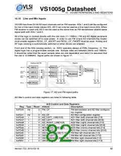
the xtal is 12.288MHz. Signal paths are shown in figure 17.
Figure 17: AD and FM signal paths
AD filter’s control and data registers are listed in following table.
A/D Control and Data Registers
Reg Type Reset Abbrev
Description
0xFE40
r/w
0
FM_CF
FM demodulator and AD filter configura-
tion register
0xFE41
0xFE46
0xFE47
0xFE48
0xFE49
0xFE4A
0xFE4B
0xFE4E
0xFE4F
0xFE50
0xFE51
r/w
0
0
0
0
0
0
0
0
0
0
0
AD_CF
AD_LEFT_LSB[15:8]
AD_LEFT
AD_RIGHT_LSB[15:8]
AD_RIGHT
MONO_AD_LSB[15:8]
MONO_AD
DEC6_LEFT_LSB[15:14]
DEC6_LEFT
DEC6_RIGHT_LSB[15:14] FM filter right channel bits [1:0]
DEC6_RIGHT FM filter right channel bits [17:2]
AD filter configuration register
AD1 filter (left) channel bits [7:0]
AD1 filter (left) channel bits [23:8]
AD2 filter (right) channel bits [7:0]
AD2 filter (right) channel bits [23:8]
AD3 filter (mono) channel bits [7:0]
AD3 filter (mono) channel bits [23:8]
FM filter left channel bits [1:0]
FM filter left channel bits [17:2]
r
r
r
r
r
r
r
r
r
r
Version: 0.2, 2012-03-16
82

 ETC [ ETC ]