VS1005g Datasheet
10 VS1005 PERIPHERALS AND REGISTERS
The default value of SP_CH0_MD0 is “00”. No other states are defined yet.
When SP_CH0_PCM is ’0’, SP_CH0_PCMM selects linear PCM mode. The default value is
“000” which corresponds to 2 audio channels without pre-emphasis.
SP_CH0_CP is a copyright bit. When ’0’, copyright for current stream is asserted.
SP_CH0_PCM is ’0’ when the audio sample word is linear PCM.
SP_CH0_PROCON is ’0’ in S/PDIF defining consumer usage. If this bit is ’1’, channel is for
professional use and the interface would be called AES/EBU. However, the channel status bits
would be different in this case.
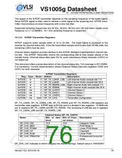
Channel Status SP_TX_CHST1
Name
Bits of data Bits of Chan- Description
word
nel status
-
15:14
13:12
11:8
7:4
31:30
29:28
27:24
23:20
19:16
Not specified, “00”
Clock Accuracy
Sampling Frequency
Channel Number
Source Number
SP_CH1_CLKA
SP_CH1_FS
SP_CH1_CH
SP_CH1_SRC
3:0
SP_CH1_CLKA indicates the level of clock accuracy the S/PDIF transmitter is capable of pro-
viding to its output.
The sampling frequency of the audio sample stream is defined in SP_CH1_FS.
SP_CH1_CH is the number of channels in the transmission. “0011” indicates two channel
stereo format.
SP_CH1_SRC is the number of sources. “0000” is defined as “do not take into account”.
Channel Status SP_TX_CHST2
Name
Bits of data Bits of Chan- Description
word
nel status
SP_ST_NWRQ
SP_TX_ENA
SP_RS1_RU
SP_RS1_RV
SP_LS1_RU
SP_LS1_RV
13
12
11
10
9
New Word Request (read only bit)
Transmitter enable
User Data bit, right channel
Validity bit, right channel
User Data bit, left channel
Validity bit, left channel
8
SP_CH2_FSO
SP_CH2_WRDL
SP_CH2_WRDLM 0
7:4
3:1
39:36
35:33
32
Original Sampling Frequency
Sample Word Length
Maximum Sample Word Length
SP_ST_NWRQ bit is set when new sample words must be written to sample word registers.
It is cleared when SP_TX_LDATA is written. Hence, SP_ST_NWRQ has the same function as
S/PDIF Interrupt, but this bit is not controlled by SP_CFG_IE.
SP_TX_ENA is the S/PDIF transmit enable. Transmitter is enabled when this register is set.
SP_RS1_RU is a user data bit for the right channel. Default value is ’0’. User data bits can be
used to convey an application specific message to the receiver. Some equipment categories
dictate the message, see IEC 60958-3.
Version: 0.2, 2012-03-16
77

 ETC [ ETC ]