TOP232-234
12
10
8
is more cost effective than the Zener clamp but requires more
careful design (see quick design checklist).
Average
Output Diode
The output diode is selected for peak inverse voltage, output
current, and thermal conditions in the application (including
heat sinking, air circulation, etc.). The higher DCMAX of
TOPSwitch-FX along with an appropriate transformer turns
ratio can allow the use of a 60 V Schoktty diode for higher
efficiency on output voltages as high as 15 V (See Figure 24. A
12 V, 30 W design using a 60 V Schottky for the output diode).
6
4
Quasi-Peak
2
Soft-Start
0
2nd
3rd
4th
5th
Generally a power supply experiences maximum stress at start-
up before the feedback loop achieves regulation. For a period
of 10 ms the on-chip soft-start linearly increases the duty cycle
from zero to the default DCMAX at turn on, which causes the
primary current and output voltage to rise in an orderly manner
allowing time for the feedback loop to take control of the duty
cycle. This reduces the stress on the TOPSwitch-FXMOSFET,
clampcircuitandoutputdiode(s),andhelpspreventtransformer
saturation during start-up. Also, soft-start limits the amount of
output voltage overshoot, and in many applications eliminates
the need for a soft-finish capacitor.
Switching Harmonic
(a)
80
70
60
50
40
30
TOPSwitch-II (no jitter)
20
-10
0
EMI
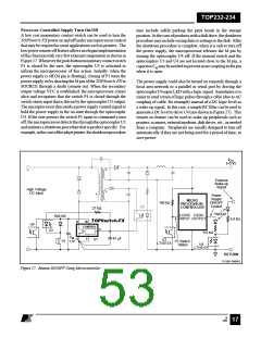
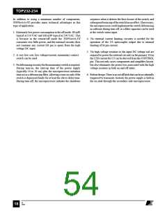
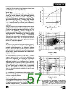
The frequency jitter feature modulates the switching frequency
over a narrow band as a means to reduce conducted EMI peaks
associated with the harmonics of the fundamental switching
frequency. This is particularly beneficial for average detection
mode. AscanbeseeninFigure28, thebenefitsofjitterincrease
with the order of the switching harmonic due to an increase in
frequency deviation.
VFG243B (QP)
VF646B (AV)
-10
-20
0.15
1
10
30
Frequency (MHz)
(b)
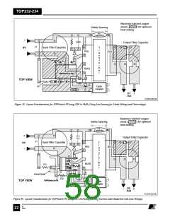
The FREQUENCY pin of TOPSwitch-FX offers a switching
frequency option of 132 kHz or 66 kHz. In applications that
require heavy snubbers on the drain node for reducing high
frequency radiated noise (for example, video noise sensitive
applications such as VCR, DVD, monitor, TV, etc.), operating
at66kHzwillreducesnubberlossresultinginbetterefficiency.
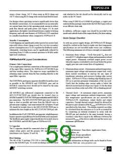
Also, in applications where transformer size is not a concern,
use of the 66 kHz option will provide lower EMI and higher
efficiency. Note that the second harmonic of 66 kHz is still
below 150 kHz, above which the conducted EMI specifications
get much tighter.
80
70
60
TOPSwitch-FX (with jitter)
50
40
30
20
-10
0
VFG243B (QP)
VF646B (AV)
For10Worbelow,itispossibletouseasimpleinductorinplace
of a more costly AC input common mode choke to meet
worldwide conducted EMI limits.
-10
-20
0.15
1
10
30
Frequency (MHz)
Transformer Design
(c)
Itisrecommendedthatthetransformerbedesignedformaximum
operating flux density of 3000 gauss and a peak flux density of
4200 gauss at maximum current limit. The turns ratio should be
chosen for a reflected voltage (VOR) no greater than 135 V when
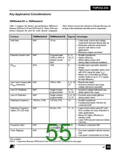
Figure 28. (a) Conducted noise improvement for low frequency
harmonics due to jitter, (b) TOPSwitch-II full range EMI
scan (100kHz, no jitter), (c) TOPSwitch-FX full range
EMI scan (132 kHz, with jitter) with identical circuitry
and conditions.
B
7/01
21

 ETC [ ETC ]