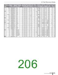
4 Diodes
Application Note
■ General Description
Surface-Mount Diodes
■
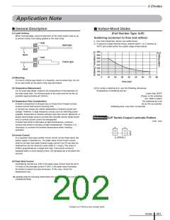
(1) Lead Forming
(Part Number Type: SJP)
When forming leads, hold the lead wire on the main body's side so as
to prevent stress from being applied to the main body.
Soldering (common to flow and reflow)
i) Use rosin based flux. Never use acidic fluxes.
Hold
ii) To prevent a large thermal stress, preheat within 1 to 2 minutes at
Axial type
150°C and solder within the usable range shown below.
300
280
260
240
220
200
180
160
Bend
Hold
Frame type
Bend
0
10
20
30
40
50
60
70
80
(2) Mounting
To mount a frame-type diode on a heatsink, use its screw hole. Do not
fix its resin body as the silicon chip may get broken.
Time (sec)
(3) Temperature Measurement
iii) For using a soldering iron, use the following references:
Temperature of soldering iron tip:
For an axial type diode, measure the temperature of the lead wire on
the main body side. The thermocouple to be used must be as thin as
possible (approximately φ0.125mm).
Lower than 300ºC
(Power of the soldering
iron: 30W or lower)
(4) Temperature Rise Consideration
The soldering tip must
be as thin as possible.
A diode’s temperature increases due to losses from forward current,
reverse current and reverse recovery time.
Soldering time: Less than 10 seconds
In normal use, losses are mainly attributable to forward current and
voltage. However, in high frequency circuits such as switching power
supplies, losses due to reverse recovery time also occurs. Moreover, in
diodes having large reverse currents like Schottky barrier diode losses
due to reverse current cannot be disregarded.
Reference
SJP Series Copper Laminate Pattern
(Unit : mm)
Forward loss tends to decrease at high temperatures. However,
reverse loss tends to increase at high temperatures. Therefore, it is
necessary to consider the ambient temperature when verifying
operation.
2.0
2.0
(5) Inrush Current
4.0 to 4.2
In a capacitor-input type rectifier circuit, inrush current flows when the
power supply is switched on. The peak value of this inrush current
shall be set less than peak forward surge current IFSM (I2t can also be
obtained but set the minimum pulse width to 1 msec). The value of
IFSM is guaranteed for a single shot only. If the inrush current is
repeated within a short period of time, the derating has to be taken into
account.
(6) Peak Value Current
Considering normal use, limit of the peak value current must be set to
10 times of the average current IF (AV). If the peak value increases.
the diode's forward loss also increases. In this case, check the
temperature rise.
● Carefully study the mounting method when the usage environment is prone to
creeping discharge.
Contact us if there is any unclear point.
Diodes
201

 ETC [ ETC ]