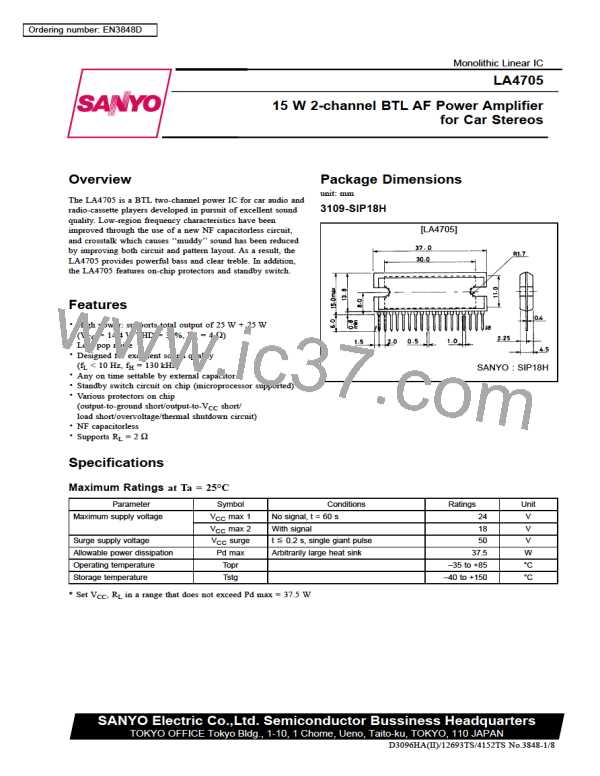
LA4705
Sample Print Pattern
Copper foil area 90 × 105 mm2
Description of External Components
C1, C4
Input capacitors
2.2 µF is recommended. f can be varied by C1, C4 capacitances to adjust the
L
bass range.
C2
Decoupling capacitor
(ripple filter)
C3
Amplifier on time setting
capacitor
Approximately 0.6 to 0.7 second for 33 µF. Since the on time is proportional to
this capacitance, it can be set as desired by varying this capacitance. The
amplifier can implement mute operation by setting C3 to GND potential.
C5
Power supply capacitor
C6, C7, C8, C9 Oscillation blocking capacitors
Use polyester film capacitors (Mylar capacitors) with good temperature
characteristics. (R2, R3, R4, and R5 used jointly.) Since stability may be
affected slightly by the pattern layout, etc., 0.1 µF or more is recommended.
R1
Standby switch current limiting
resistor
10 kΩ is recommended. This resistor cannot be removed.
No.3848 -4/8

 ETC [ ETC ]