ST90158 - TIMER/WATCHDOG (WDT)
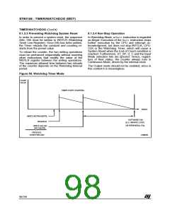
9.1.3 Watchdog Timer Operation
TIMER/WATCHDOG (Cont’d)
9.1.2.7 Gated Input Mode
This mode can be used for pulse width measure-
ment. The Timer is clocked by INTCLK/4, and is
started and stopped by means of the input pin and
the ST_SP bit. When the input pin is high, the Tim-
er counts. When it is low, counting stops. The
maximum input pin frequency is equivalent to
INTCLK/8.
This mode is used to detect the occurrence of a
software fault, usually generated by external inter-
ference or by unforeseen logical conditions, which
causes the application program to abandon its
normal sequence of operation. The Watchdog,
when enabled, resets the MCU, unless the pro-
gram executes the correct write sequence before
expiry of the programmed time period. The appli-
cation program must be designed so as to correct-
ly write to the WDTLR Watchdog register at regu-
lar intervals during all phases of normal operation.
9.1.2.8 Triggerable Input Mode
The Timer (clocked internally by INTCLK/4) is
started by the following sequence:
– setting the Start-Stop bit, followed by
– a High to Low transition on the input pin.
To stop the Timer, reset the ST_SP bit.
9.1.2.9 Retriggerable Input Mode
9.1.3.1
Watchdog
Hardware
Watchdog/Software
The HW0SW1 pin (when available) selects Hard-
ware Watchdog or Software Watchdog.
If HW0SW1 is held low:
In this mode, the Timer (clocked internally by
INTCLK/4) is started by setting the ST_SP bit. A
High to Low transition on the input pin causes
counting to restart from the initial value. When the
Timer is stopped (ST_SP bit reset), a High to Low
transition of the input pin has no effect.
– The Watchdog is enabled by hardware immedi-
ately after an external reset. (Note: Software re-
set or Watchdog reset have no effect on the
Watchdog enable status).
– The initial counter value (FFFFh) cannot be mod-
ified, however software can change the prescaler
value on the fly.
9.1.2.10 Timer/Counter Output Modes
Output modes are selected by means of the OUT-
EN (Output Enable) and OUTMD (Output Mode)
bits of the WDTCR register.
– The WDGEN bit has no effect. (Note: it is not
forced low).
If HW0SW1 is held high, or is not present:
No Output Mode
(OUTEN = “0”)
– The Watchdog can be enabled by resetting the
WDGEN bit.
The output is disabled and the corresponding pin
is set high, in order to allow other alternate func-
tions to use the I/O pin.
9.1.3.2 Starting the Watchdog
In Watchdog mode the Timer is clocked by
INTCLK/4.
Square Wave Output Mode
(OUTEN = “1”, OUTMD = “0”)
If the Watchdog is software enabled, the time base
must be written in the timer registers before enter-
ing Watchdog mode by resetting the WDGEN bit.
Once reset, this bit cannot be changed by soft-
ware.
The Timer outputs a signal with a frequency equal
to half the End of Count repetition rate on the WD-
OUT pin. With an INTCLK frequency of 20MHz,
this allows a square wave signal to be generated
whose period can range from 400ns to 6.7 sec-
onds.
If the Watchdog is hardware enabled, the time
base is fixed by the reset value of the registers.
Pulse Width Modulated Output Mode
(OUTEN = “1”, OUTMD = “1”)
Resetting WDGEN causes the counter to start, re-
gardless of the value of the Start-Stop bit.
The state of the WROUT bit is transferred to the
output pin (WDOUT) at the End of Count, and is
held until the next End of Count condition. The
user can thus generate PWM signals by modifying
the status of the WROUT pin between End of
Count events, based on software counters decre-
mented by the Timer Watchdog interrupt.
In Watchdog mode, only the Prescaler Constant
may be modified.
If the End of Count condition is reached a System
Reset is generated.
97/199
9

 ETC [ ETC ]