ST90158 - TIMER/WATCHDOG (WDT)
TIMER/WATCHDOG (Cont’d)
9.1.2 Functional Description
9.1.2.1 External Signals
9.1.2.4 Single/Continuous Mode
The S_C bit allows selection of single or continu-
ous mode.This Mode bit can be written with the
Timer stopped or running. It is possible to toggle
the S_C bit and start the counter with the same in-
struction.
The HW0SW1 pin can be used to permanently en-
able Watchdog mode. Refer to section 9.1.3.1 on
page 97.
The WDIN Input pin can be used in one of four
modes:
Single Mode
On reaching the End Of Count condition, the Timer
stops, reloads the constant, and resets the Start/
Stop bit. Software can check the current status by
reading this bit. To restart the Timer, set the Start/
Stop bit.
– Event Counter Mode
– Gated External Input Mode
– Triggerable Input Mode
– Retriggerable Input Mode
Note: If the Timer constant has been modified dur-
ing the stop period, it is reloaded at start time.
The WDOUT output pin can be used to generate a
square wave or a Pulse Width Modulated signal.
Continuous Mode
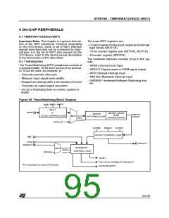
An interrupt, generated when the WDT is running
as the 16-bit Timer/Counter, can be used as a Top
Level Interrupt or as an interrupt source connected
to channel A0 of the external interrupt structure
(replacing the INT0 interrupt input).
On reaching the End Of Count condition, the coun-
ter automatically reloads the constant and restarts.
It is stopped only if the Start/Stop bit is reset.
9.1.2.5 Input Section
The counter can be driven either by an external
clock, or internally by INTCLK divided by 4.
If the Timer/Counter input is enabled (INEN bit) it
can count pulses input on the WDIN pin. Other-
wise it counts the internal clock/4.
9.1.2.2 Initialisation
For instance, when INTCLK = 24MHz, the End Of
Count rate is:
The prescaler (WDTPR) and counter (WDTRL,
WDTRH) registers must be loaded with initial val-
ues before starting the Timer/Counter. If this is not
done, counting will start with reset values.
2.79 seconds for Maximum Count
(Timer Const. = FFFFh, Prescaler Const. = FFh)
9.1.2.3 Start/Stop
166 ns for Minimum Count
(Timer Const. = 0000h, Prescaler Const. = 00h)
The ST_SP bit enables downcounting. When this
bit is set, the Timer will start at the beginning of the
following instruction. Resetting this bit stops the
counter.
The Input pin can be used in one of four modes:
– Event Counter Mode
– Gated External Input Mode
If the counter is stopped and restarted, counting
will resume from the last value unless a new con-
stant has been entered in the Timer registers
(WDTRL, WDTRH).
– Triggerable Input Mode
– Retriggerable Input Mode
The mode is configurable in the WDTCR.
9.1.2.6 Event Counter Mode
A new constant can be written in the WDTRH,
WDTRL, WDTPR registers while the counter is
running. The new value of the WDTRH, WDTRL
registers will be loaded at the next End of Count
(EOC) condition while the new value of the
WDTPR register will be effective immediately.
In this mode the Timer is driven by the external
clock applied to the input pin, thus operating as an
event counter. The event is defined as a high to
low transition of the input signal. Spacing between
trailing edges should be at least 8 INTCLK periods
(or 333ns with INTCLK = 24MHz).
End of Count is when the counter is 0.
When Watchdog mode is enabled the state of the
ST_SP bit is irrelevant.
Counting starts at the next input event after the
ST_SP bit is set and stops when the ST_SP bit is
reset.
96/199
9

 ETC [ ETC ]