ST90158 - TIMER/WATCHDOG (WDT)
9 ON-CHIP PERIPHERALS
9.1 TIMER/WATCHDOG (WDT)
Important Note: This chapter is a generic descrip-
tion of the WDT peripheral. However depending
on the ST9 device, some or all of WDT interface
signals described may not be connected to exter-
nal pins. For the list of WDT pins present on the
ST9 device, refer to the device pinout description
in the first section of the data sheet.
The main WDT registers are:
– Control register for the input, output and interrupt
logic blocks (WDTCR)
– 16-bit counter register pair (WDTHR, WDTLR)
– Prescaler register (WDTPR)
The hardware interface consists of up to five sig-
nals:
9.1.1 Introduction
The Timer/Watchdog (WDT) peripheral consists of
a programmable 16-bit timer and an 8-bit prescal-
er. It can be used, for example, to:
– WDIN External clock input
– WDOUT Square wave or PWM signal output
– INT0 External interrupt input
– Generate periodic interrupts
– NMI Non-Maskable Interrupt input
– Measure input signal pulse widths
– Request an interrupt after a set number of events
– Generate an output signal waveform
– HW0SW1 Hardware/Software Watchdog ena-
ble.
– Act as a Watchdog timer to monitor system in-
tegrity
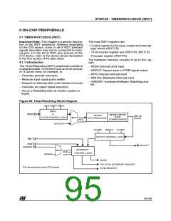
Figure 55. Timer/Watchdog Block Diagram
INMD1 INMD2
INEN
INPUT
&
1
WDIN
WDTRH, WDTRL
WDTPR
END OF
16-BIT
CLOCK CONTROL LOGIC
MUX
8-BIT PRESCALER
COUNT
DOWNCOUNTER
WDT
CLOCK
INTCLK/4
WROUT
OUTEN
OUTMD
OUTPUT CONTROL LOGIC
1
NMI
1
INT0
1
WDOUT
1
HW0SW1
INTERRUPT
MUX
IAOS
CONTROL LOGIC
WDGEN
TLIS
RESET
TOP LEVEL INTERRUPT REQUEST
INTA0 REQUEST
1
Pin not present on some ST9 devices.
95/199
9

 ETC [ ETC ]