ST90158 - DEVICE ARCHITECTURE
2.8 MMU USAGE
2.8.1 Normal Program Execution
Program memory is organized as a set of 64-
Kbyte segments. The program can span as many
segments as needed, but a procedure cannot
stretch across segment boundaries. jps, calls
and retsinstructions, which automatically modify
the CSR, must be used to jump across segment
boundaries. Writing to the CSR is forbidden during
normal program execution because it is not syn-
chronized with the opcode fetch. This could result
in fetching the first byte of an instruction from one
memory segment and the second byte from anoth-
er. Writing to the CSR is allowed when it is not be-
ing used, i.e during an interrupt service routine if
ENCSR is reset.
used instead of the CSR, and the interrupt stack
frame is kept exactly as in the original ST9 (only
the PC and flags are pushed). This avoids the
need to save the CSR on the stack in the case of
an interrupt, ensuring a fast interrupt response
time. The drawback is that it is not possible for an
interrupt service routine to perform segment
calls/jps: these instructions would update the
CSR, which, in this case, is not used (ISR is used
instead). The code size of all interrupt service rou-
tines is thus limited to 64 Kbytes.
If, instead, bit 6 of the EMR2 register is set, the
ISR is used only to point to the interrupt vector ta-
ble and to initialize the CSR at the beginning of the
interrupt service routine: the old CSR is pushed
onto the stack together with the PC and the flags,
and then the CSR is loaded with the ISR. In this
case, an iret will also restore the CSR from the
stack. This approach lets interrupt service routines
access the whole 4-Mbyte address space. The
drawback is that the interrupt response time is
slightly increased, because of the need to also
save the CSR on the stack. Compatibility with the
original ST9 is also lost in this case, because the
interrupt stack frame is different; this difference,
however, would not be noticeable for a vast major-
ity of programs.
Note that a routine must always be called in the
same way, i.e. either always with callor always
with calls, depending on whether the routine
ends with ret or rets. This means that if the rou-
tine is written without prior knowledge of the loca-
tion of other routines which call it, and all the pro-
gram code does not fit into a single 64-Kbyte seg-
ment, then calls/retsshould be used.
In typical microcontroller applications, less than 64
Kbytes of RAM are used, so the four Data space
pages are normally sufficient, and no change of
DPR[3:0] is needed during Program execution. It
may be useful however to map part of the ROM
into the data space if it contains strings, tables, bit
maps, etc.
Data memory mapping is independent of the value
of bit 6 of the EMR2 register, and remains the
same as for normal code execution: the stack is
the same as that used by the main program, as in
the ST9. If the interrupt service routine needs to
access additional Data memory, it must save one
(or more) of the DPRs, load it with the needed
memory page and restore it before completion.
If there is to be frequent use of paging, the user
can set bit 5 (DPRREM) in register R246 (EMR2)
of Page 21. This swaps the location of registers
DPR[3:0] with that of the data registers of Ports 0-
3. In this way, DPR registers can be accessed
without the need to save/set/restore the Page
Pointer Register. Port registers are therefore
moved to page 21. Applications that require a lot of
paging typically use more than 64 Kbytes of exter-
nal memory, and as ports 0, 1 and 2 are required
to address it, their data registers are unused.
2.8.3 DMA
Depending on the PS bit in the DAPR register (see
DMA chapter) DMA uses either the ISR or the
DMASR for memory accesses: this guarantees
that a DMA will always find its memory seg-
ment(s), no matter what segment changes the ap-
plication has performed. Unlike interrupts, DMA
transactions cannot save/restore paging registers,
so a dedicated segment register (DMASR) has
been created. Having only one register of this kind
means that all DMA accesses should be pro-
grammed in one of the two following segments:
the one pointed to by the ISR (when the PS bit of
the DAPR register is reset), and the one refer-
enced by the DMASR (when the PS bit is set).
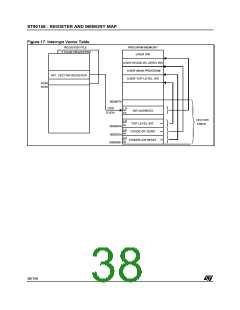
2.8.2 Interrupts
The ISR register has been created so that the in-
terrupt routines may be found by means of the
same vector table even after a segment jump/call.
When an interrupt occurs, the CPU behaves in
one of 2 ways, depending on the value of the ENC-
SR bit in the EMR2 register (R246 on Page 21).
If this bit is reset (default condition), the CPU
works in original ST9 compatibility mode. For the
duration of the interrupt service routine, the ISR is
36/199
9

 ETC [ ETC ]