ST90158 - SERIAL PERIPHERAL INTERFACE (SPI)
SERIAL PERIPHERAL INTERFACE (Cont’d)
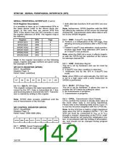
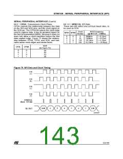
Bit 2 = CPHA: Transmission Clock Phase.
Bit 1:0 = SPR[1:0]: SPI Rate.
These two bits select one (of four) baud rates, to
be used as SCK.
CPHA controls the relationship between the data
on the SDI and SDO pins, and the clock signal on
the SCK pin. The CPHA bit selects the clock edge
used to capture data. It has its greatest impact on
the first bit transmitted (MSB), because it does (or
does not) allow a clock transition before the first
data capture edge. Figure 75 shows the relation-
ship between CPHA, CPOL and SCK, and indi-
cates active clock edges and strobe times.
Clock
Divider
SCK Frequency
(@ INTCLK = 24MHz)
SPR1 SPR0
0
0
1
1
0
1
0
1
8
16
128
256
3000kHz
(T = 0.33µs)
(T = 0.67µs)
(T = 5.33µs)
(T = 10.66µs)
1500kHz
187.5kHz
93.75kHz
SCK
(in Figure 75)
CPOL
CPHA
0
0
1
1
0
1
0
1
(a)
(b)
(c)
(d)
Figure 75. SPI Data and Clock Timing
143/199
9

 ETC [ ETC ]