ST90158 - SERIAL PERIPHERAL INTERFACE (SPI)
SERIAL PERIPHERAL INTERFACE (Cont’d)
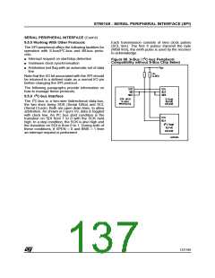
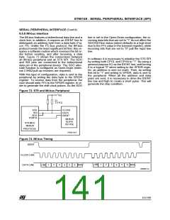
9.5.5 Working With Other Protocols
Each transmission consists of nine clock pulses
(SCL line). The first 8 pulses transmit the byte
(MSB first), the ninth pulse is used by the receiver
The SPI peripheral offers the following facilities for
2
operation with S-bus/I C-bus and IM-bus proto-
to acknowledge.
cols:
2
■ Interrupt request on start/stop detection
■ Hardware clock synchronisation
Figure 68. S-Bus / I C-bus Peripheral
Compatibility without S-Bus Chip Select
■ Arbitration lost flag with an automatic set of data
line
Note that the I/O bit associated with the SPI should
be returned to a defined state as a normal I/O pin
before changing the SPI protocol.
The following paragraphs provide information on
how to manage these protocols.
2
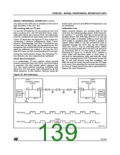
9.5.6 I C-bus Interface
2
The I C-bus is a two-wire bidirectional data-bus,
the two lines being SDA (Serial DAta) and SCL
(Serial CLock). Both are open drain lines, to allow
arbitration. As shown in Figure 69, data is toggled
with clock low. An I²C bus start condition is the
transition on SDI from 1 to 0 with the SCK held
high. In a stop condition, the SCK is also high and
the transition on SDI is from 0 to 1. During both of
these conditions, if SPEN = 0 and BMS = 1 then
an interrupt request is performed.
137/199
9

 ETC [ ETC ]