ST72104G, ST72215G, ST72216G, ST72254G
1 INTRODUCTION
The ST72104G, ST72215G, ST72216G and
ST72254G devices are members of the ST7 mi-
crocontroller family. They can be grouped as fol-
lows:
Under software control, all devices can be placed
in WAIT, SLOW, or HALT mode, reducing power
consumption when the application is in idle or
stand-by state.
– ST72254G devices are designed for mid-range
applications with ADC and I²C interface capabili-
ties.
The enhanced instruction set and addressing
modes of the ST7 offer both power and flexibility to
software developers, enabling the design of highly
efficient and compact application code. In addition
to standard 8-bit data management, all ST7 micro-
controllers feature true bit manipulation, 8x8 un-
signed multiplication and indirect addressing
modes.
– ST72215/6G devices target the same range of
applications but without I²C interface.
– ST72104G devices are for applications that do
not need ADC and I²C peripherals.
All devices are based on a common industry-
standard 8-bit core, featuring an enhanced instruc-
tion set.
For easy reference, all parametric data are located
in Section 14 on page 96.
The ST72C104G, ST72C215G, ST72C216G and
ST72C254G versions feature single-voltage
FLASH memory with byte-by-byte In-Situ Pro-
gramming (ISP) capability.
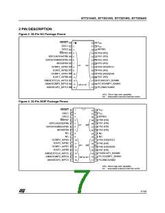
Figure 1. General Block Diagram
Internal
CLOCK
OSC1
OSC2
MULTI OSC
+
CLOCK FILTER
2
I C
PA7:0
(8 bits)
PORT A
LVD
V
SPI
DD
POWER
SUPPLY
PB7:0
(8 bits)
V
SS
PORT B
16-BIT TIMER A
PORT C
RESET
CONTROL
8-BIT CORE
ALU
PC5:0
(6 bits)
PROGRAM
MEMORY
8-BIT ADC
(4 or 8K Bytes)
16-BIT TIMER B
RAM
(256 Bytes)
WATCHDOG
6/140
4

 ETC [ ETC ]