JMicron/JM20329
Signal Name
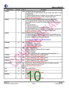
GPIO[1]
Pin No.
Type
Description
29
DIOH EEPROM 9346 Data Input (DI) /GPIO1
(1) After power on status detecting, this pin becomes Data Input of serial
EEPROM 9346.
(2) While EEPROM detection is complete, this pin is default set to input, and
could act as GPIO pin by SCSI-2 vender command (button input).
Input in USB Suspend mode(F)
GPIO[2]
28
DIOH USB Attach Sequence/EEPROM 9346 Serial Clock (SK)/GPIO2
(1) The internal controller will detect the pin status after power on. The
functionality of power on initial state determines the USB attach sequence of
JM20329
0: Attached USB first.
1: Check SATA device first.
(2) This pin is Serial Clock of serial EEPROM 9346.
(3) While EEPROM detection is complete, this pin is default set to input, and
could act as GPIO pin by SCSI-2 vender command (button input).
Input in USB Suspend mode (F)
GPIO[3]
27
DIOH EEPROM 9346 Chip Select (CS) /GPIO3
(1) This pin functions as Chip Select of EEPROM 9346 in EEPRM detection.
(2) While EEPROM detection is complete, this pin is default set to input, and
could act as GPIO pin by SCSI-2 vender command.
Note that it only supports 9346 with 64x16-bit mode.
Input in USB Suspend mode (F)
PTMODE
GPIO[7]
34
6
DIH Protocol mode
1: Enable USB to SATA function.
0: Disable USB and SATA function.
Input in USB Suspend mode (F)
DIO GPIO 7: USB Bus State.
This pin will go high while the USB Vbus is applied.
It will go low only in
(1) Vbus is detached.
(2) Vbus is attached and USB is configured and enter suspend state. (F)
GPIO[18]
48
1
DIO
DIO
DIO
Can be configured by SCSI-2 vender command.
Output to “0” in USB Suspend mode(F)
Can be configured by SCSI-2 vender command.
Output to “0” in USB Suspend mode(F)
Can be configured by SCSI-2 vender command
Output to “0” in USB Suspend mode. (F)
GPIO[22]
GPIO[23]
2
Reserved[3:0]
47,46,38
,37
DIO Reserved Pins. They are for internal used only. We strongly recommend
DIO customer to make Reserved[3:0] = 0011.
DIOH Input in USB Suspend mode (F)
DIOH
UAI
39
40
32
DIH 8051 UART interface.
Input in USB Suspend mode
UAO
DO
DO
8051 UART interface.
Output to “1” in USB Suspend mode.
SATA PHY is ready.
PHYRDY
0: SATA interface not established.
1: SATA interface established.
Output to “0” in USB Suspend mode.
Version 1.0
May 2007
© JMicron 2007. All rights reserved.
Page 10
Copying prohibited.

 ETC [ ETC ]