Philips Semiconductors
Product specification
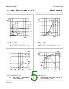
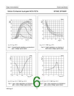
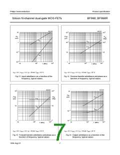
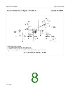
Silicon N-channel dual-gate MOS-FETs
BF998; BF998R
THERMAL CHARACTERISTICS
SYMBOL
PARAMETER
CONDITIONS
VALUE
UNIT
Rth j-a
thermal resistance from junction to ambient in free air; BF998 note 1
note 2
460
500
500
K/W
K/W
K/W
Rth j-a
thermal resistance from junction to ambient in free air; BF998R note 1
Notes
1. Device mounted on a ceramic substrate, 8 mm × 10 mm × 0.7 mm.
2. Device mounted on a printed-circuit board.
STATIC CHARACTERISTICS
Tj = 25 °C; unless otherwise specified.
SYMBOL
PARAMETER
CONDITIONS
MIN. MAX. UNIT
±V(BR)G1-SS gate 1-source breakdown voltage
±V(BR)G2-SS gate 2-source breakdown voltage
VG2-S = VDS = 0; IG1-SS = ±10 mA
VG1-S = VDS = 0; IG2-SS = ±10 mA
VG2-S = 4 V; VDS = 8 V; ID = 20 µA
VG1-S = 0; VDS = 8 V; ID = 20 µA
VG2-S = 4 V; VDS = 8 V; VG1-S = 0; note 1
VG2-S = VDS = 0; VG1-S = ±5 V
VG1-S = VDS = 0; VG2-S = ±5 V
6
6
−
−
2
−
−
20
20
2.0
1.5
18
50
50
V
V
−V(P)G1-S
−V(P)G2-S
IDSS
gate 1-source cut-off voltage
gate 2-source cut-off voltage
drain-source current
V
V
mA
nA
nA
±IG1-SS
±IG2-SS
gate 1 cut-off current
gate 2 cut-off current
Note
1. Measured under pulse condition.
DYNAMIC CHARACTERISTICS
Common source; Tamb = 25 °C; VDS = 8 V; VG2-S = 4 V; ID = 10 mA.
SYMBOL
yfs
PARAMETER
forward transfer admittance
input capacitance at gate 1
input capacitance at gate 2
output capacitance
CONDITIONS
MIN. TYP. MAX. UNIT
f = 1 kHz
f = 1 MHz
f = 1 MHz
f = 1 MHz
f = 1 MHz
21
−
24
−
mS
pF
pF
pF
fF
Cig1-s
Cig2-s
Cos
2.1
1.2
1.05
25
2.5
−
−
−
−
Crs
reverse transfer capacitance
noise figure
−
−
F
f = 200 MHz; GS = 2 mS; BS = BSopt
f = 800 MHz; GS = 3.3 mS; BS = BSopt
−
0.6
1.0
−
dB
dB
−
−
1996 Aug 01
4

 ETC [ ETC ]