CY545 Stepper System Controller
www.ControlChips.com
CHAPTER 9 - OPERATING MODE COMMAND
Operating Mode Command
Another command is used to define the Operating mode of the CY545. It is:
O Mode Set CY545 operating mode
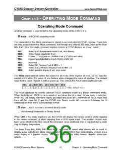
The parameter of the Mode command is stored in an 8-bit internal CY545 register. These bits
are only accessible by the Mode command, not through any external I/O lines, such as the User
Bits. Each bit of the Mode command register controls a CY545 feature, as shown below:
MB7
MB6
MB5
MB4
Select ASCII command mode if set, else Binary
Select serial baud rate if set
Enable CTS/ signal on USRB6 if set (CY545A and later)
Display position during Jog & Home cmd if set
MB3
MB2
MB1
MB0
reserved
Select HP Display if set & MB0 = 1
Select CY325 based display if set & MB0 = 0
Select parallel display if set, else serial
The Mode command will define the values for all 8 bits of the register at once, so you must be
careful not to affect the value of one feature while changing the value of another. The default
value for the mode register is 80H at power up. This selects the ASCII command mode with
The most significant bit selects between ASCII command mode and Binary command mode.
When the bit is set, ASCII mode is selected, and when the bit is clear, Binary mode is selected.
When you use Binary command mode, you must first issue an O command in ASCII mode that
turns off the upper bit, to put the CY545 into Binary mode. All commands following the O
command are then in the special Binary format:
O 0<cr> ASCII command to select Binary mode
... All following commands in Binary format
When MB4 of the mode register is set, the CY545 will display the current position while stepping
in the Home command or while stepping from a JOG signal input. This position display may
have some effect on the step rate of the command, since additional time is required during each
step to display the position.
The lower three bits, MB0, MB1, and MB2, are used to select what device will be used to
display query outputs and string value outputs from the CY545. Two basic display choices are a
serial display or a parallel display. The least significant bit, MB0, selects between these two
options.
© 2002 Cybernetic Micro Systems
31
Chapter 9 - Operating Mode Command

 ETC [ ETC ]