15
15
15
8
8
8
7
7
7
0
0
0
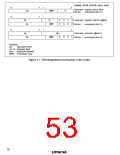
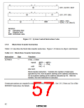
op
RTE, SLEEP, NOP
LDC, STC (Rn)
op
rn
ANDC, ORC,
XORC, LDC (#xx:8)
op
IMM
Notation:
op: Operation field
rn: Register field
IMM: Immediate data
Figure 2-9 System Control Instruction Codes
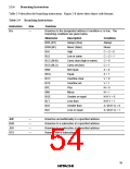
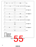
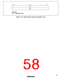
Block Data Transfer Instruction
2.5.8
Table 2-11 describes the block data transfer instruction. Figure 2-10 shows its object code format.
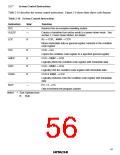
Table 2-11 Block Data Transfer Instruction
Instruction
Size
Function
If R4L ≠ 0 then
repeat
EEPMOV
—
@R5+ → @R6+
R4L – 1 → R4L
R4L = 0
until
else next;
Block transfer instruction. Transfers the number of data bytes
specified by R4L from locations starting at the address indicated by
R5 to locations starting at the address indicated by R6. After the
transfer, the next instruction is executed.
Certain precautions are required in using the EEPMOV instruction. See 2.9.3, Notes on Use of the
EEPMOV Instruction, for details.
42

 ETC [ ETC ]