2. Operation in Asynchronous Mode
In asynchronous mode, serial communication is performed with synchronization provided
character by character. A start bit indicating the start of communication and one or two stop bits
indicating the end of communication are added to each character before it is sent.
SCI3 has separate transmission and reception units, allowing full-duplex communication. As the
transmission and reception units are both double-buffered, data can be written during transmission
and read during reception, making possible continuous transmission and reception.
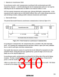
a. Data transfer format
The general data transfer format in asynchronous communication is shown in figure 10-8.
(LSB)
(MSB)
1
Serial Start
Parity
bit
Stop
bit(s)
Mark
state
Transmit/receive data
5, 7 or 8 bits
data
bit
1 bit
1 or 2 bits
1 bit
or none
One transfer data unit (character or frame)
Figure 10-8 Data Format in Asynchronous Communication
In asynchronous communication, the communication line is normally in the mark state (high
level). SCI3 monitors the communication line and when it detects a space (low level), identifies
this as a start bit and begins serial data communication.
One transfer data character consists of a start bit (low level), followed by transmit/receive data
(LSB-first format, starting from the least significant bit), a parity bit (high or low level), and
finally one or two stop bits (high level).
In asynchronous mode, synchronization is performed by the falling edge of the start bit during
reception. The data is sampled on the 8th pulse of a clock with a frequency 16 times the bit
period, so that the transfer data is latched at the center of each bit.
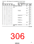
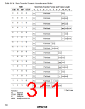
Table 10-14 shows the 12 data transfer formats that can be set in asynchronous mode. The format
is selected by the settings in the serial mode register (SMR).
295

 ETC [ ETC ]