REED
RELAYS
APPLICATION DATA
ELECTRICAL CHARACTERISTICS (Continued)
RELEASE TIME (Continued)
NOISE
Noise is defined as a voltage appearing between terminals of a switch for a
few milliseconds following closure of the contacts. It occurs because the
reeds (blades) are moving in a magnetic field and because voltages are
produced within them by magnetostrictive effects. From an application
standpoint, noise is important if the signal switched by the reed is to be used
within a few milliseconds immediately following closure of the contacts.
When noise is critical in an application, a peak-to-peak limit must be
established by measurement techniques, including filters which must be
specified for that particular switching application.
If the relay coil is suppressed, release times are increased. Diode suppres-
sion can delay release times for several milliseconds, depending on coil
characteristics, coil voltage, and reed release characteristics.
CONTACT BOUNCE
Dry reed contacts bounce on closure as with any other hard contact relay.
The duration of bounce on a Dry reed switch is typically very short, and is
in part dependent on drive level. In some of the faster devices, the sum of
the operate time and bounce is relatively constant. As drive is increased, the
operate time decreases with bounce time increasing.
ENVIRONMENTAL CHARACTERISTICS
The normally closed contacts of a SPDT switch bounce more then the
normally open contacts. Magnetically biased SPST-NC contacts exhibit
essentially the same bounce characteristics as SPST-NO switches.
Reed relays are used in essentially the same environments as other types of
relays. Factors influencing their ability to function would be
temperature extremes beyond specified limits
CONTACT RESISTANCE
VIBRATION
The reeds (blades) in a dry reed switch are made of magnetic material
which has a high volume resistivity, terminal-to-terminal resistance is
somewhat higher than in some other types of relays. Typical specification
limits for initial resistance of a SPST-NO reed relay is 0.200 ohms max
(200 milliohms).
The reed switch structure, with so few elements free to move, has a better
defined response to vibration than other relay types. With vibration inputs
reasonably separated from the resonant frequency, the reed relay will
withstand relatively high inputs, 20 g's or more. At resonance of the reeds,
the typical device can fail at very low input levels. Typical resonance
frequency is 2000 hz.
INSULATION RESISTANCE
SHOCK
A dry reed switch made in a properly controlled internal atmosphere will
have an insulation resistance of 1012 to 1013 ohms or greater. When it is
assembled into a relay, parallel insulation paths reduce this to typical values
of 109 ohms. Depending on the particular manner of relay construction,
exposure to high humidity or contaminating environments can appreciably
lower final insulation resistance.
Dry reed relays will withstand relatively high levels of shock. SPST-NO
contacts are usually rated to pass 30 to 50 g's, 11 milliseconds, half sign
wave shock, without false operation of contacts. Switches exposed to a
magnetic field that keep the contacts in a closed position, such as in the
biased latching form, demonstrate somewhat lower resistance to shock.
Normally closed contacts of mechanically biased SPDT switches may also
fail at lower shock levels.
CAPACITANCE.
Reed capsules typically have low terminal-to-terminal capacitance.
However, in the typicall relay structure where the switch is surrounded by a
coil, capacitance from each reed to the coil act to increase capacitance
many times. If the increased capacitance is objectionable, it can be
reduced by placing a grounded electrostatic shield between the switch and
coil.
TEMPERATURE
Differential expansion or contraction of reed switches and materials used in
relay assemblies can lead to fracture of the switches. Reed relays are
capable of withstanding temperature cycling or temperature shock over a
range of at least -50˚C to + 100˚C. These limits should be applied to the
application to prevent switch failure.
DIELECTRIC WITHSTAND VOLTAGE
CONTACT PROTECTION
With the exception of the High-Voltage dry reed switches ( capsules that
are pressurized or evacuated), the dielectric strength limitation of relays is
determined by the ampere turn sensitivity of the switches used. A typical
limit is 200 VAC. The dielectric withstand voltage between switch and coil
terminals is usually 500 VAC.
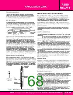
Tungsten lamp, inductive and capacitive discharge load are extremely
detrimental to reed switches and reduce life considerably. Illustrated below
are typical suppression circuits which are necessary for maximum contact
life.
FIGURE 3
THERMAL EMF
Input
Input
R
R
Since thermally generated voltages result from thermal gradients within the
relay assembly, relays built to minimize this effect often use sensitive
switches to reduce required coil power, and thermally conductive materials
to reduce temperature gradients. Latching relays, which may be operated
by a short duration pulse, are often used if the operational rate is not
changed for longer periods of time because coil power is not required to
keep the relay in the on or off position after the initial turn on or turn off
pulse.
Initial turn-on current is generally 10 times higher than the rated
operating current of the lamp. A current limiting resistor in series with
the load, or a bleeder resistor across the contacts will suppress the
inrush current. Thesesame circuits can be used with capacitive loads,
as shown in Figure 3.
FIGURE 4
Input
Input
DC inductive loads call for either a diode or a thyristor to be placed across
the load. These circuits are necessary to protect the contacts
when inductive loads are to be switched in a circuit, as shown in Figure 4.
WEBSITE: www.magnecraft.com EMAIL:info@magnecraft.com FAX ON DEMAND 1-800/891-2957, DOCUMENT 100
PAGE 69

 ETC [ ETC ]