Features
Applications
■ Available in E6 series
■ Unit height of 1.1 mm
■ Current up to 10ꢀꢀ mA
■ Lead free
■ Input/output of DC/DC converters
■ Power supplies for:
• Portable communication equipment
• Camcorders
• LCD TVs
• Car radios
220
■ RoHS compliant*
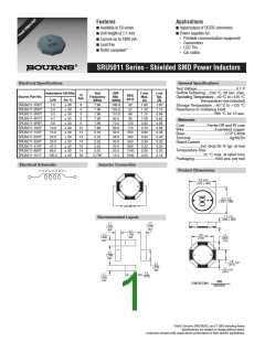
SRU5011 Series - Shielded SMD Power Inductors
Electrical Specifications
General Specifications
Test Voltage.....................................0.1 V
Reflow Soldering....230 °C, 50 sec. max.
Operating Temperature..-40 °C to +125 °C
(Temperature rise included)
Storage Temperature ..-40 °C to +125 °C
Resistance to Soldering Heat
Inductance 100 KHz
Test
Frequency
(MHz)
SRF
Min.
(MHz)
I rms
Max.
(A)
I sat
Typ.
(A)
Q
Ref.
RDC
(mΩ)
Bourns Part No.
(µH)
1.5
Tol. %
30
SRU5011-1R5Y
SRU5011-2R5Y
SRU5011-3R3Y
SRU5011-4R7Y
SRU5011-6R8Y
SRU5011-100Y
SRU5011-150Y
SRU5011-220Y
SRU5011-330Y
SRU5011-470Y
SRU5011-680Y
SRU5011-101Y
8
8
8
8
8
12
12
14
14
16
14
30
7.96
7.96
7.96
7.96
7.96
7.96
2.52
2.52
2.52
2.52
2.52
0.796
195.0
125.0
110.0
85.0
70.0
50.0
42.0
38.0
30.0
25.0
20.0
15.0
32
52
66
1.80
1.30
1.15
1.00
0.82
0.70
0.60
0.50
0.38
0.32
0.26
0.20
1.50
1.10
0.94
0.82
0.68
0.58
0.48
0.40
0.30
0.26
0.22
0.18
2.5
30
................................260 °C for 10 sec.
3.3
30
4.7
30
95
Materials
6.8
30
130
170
250
380
550
800
1240
1600
Core .....................Ferrite DR and RI core
Wire .............................Enameled copper
Base ......................................LCP E4008
Terminal ....................................Ag/Ni/Sn
Rated Current
....................Ind. drop 35 % typ. at Isat
Temperature Rise
10.0
15.0
22.0
33.0
47.0
68.0
100.0
30
30
30
30
30
30
30
.......................25 °C max. at rated Irms
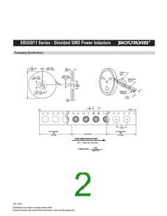
Packaging...................1500 pcs. per reel
Electrical Schematic
Inductor Connection
Product Dimensions
5.2 ꢀ.2
(.2ꢀ5 .ꢀꢀ08
5.2 ꢀ.2
(.2ꢀ5 .ꢀꢀ08
LCR METER
1.1 ꢀ.1
(.ꢀ43 .ꢀꢀ48
Recommended Layout
1.1
(.ꢀ438
REF.
1.1
(.ꢀ438
REF.
3.7
1.1
(.ꢀ438
REF.
(.1468
REF.
1.7
(.ꢀ678
TYP.
3.9
(.1548
TYP.
3.7
(.1468
REF.
1.0
(.ꢀ718
TYP.
2.ꢀ
(.ꢀ798
REF.
1.7
(.ꢀ678
TYP.
2.ꢀ
(.ꢀ798
1.1
REF.
(.ꢀ438
REF.
MM
(INCHES8
DIMENSIONS:
*RoHS Directive 2ꢀꢀ2/95/EC Jan 27 2ꢀꢀ3 including Annex
Specifications are subject to change without notice.
Customers should verify actual device performance in their specific applications.

 ETC [ ETC ]