TrueSpeech® Co-Processor
PRELIMINARY/CONFIDENTIAL
Version: 1.18
A.1
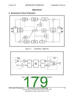
Introduction
Implementation of a speakerphone system involves three primary sections:
•
•
•
external analog circuitry
physical acoustic devices
digital canceller (provided by the CT8022)
Optimum speakerphone performance can only be achieved by the correct design and use of all three sections.
A.2
Analog Circuitry
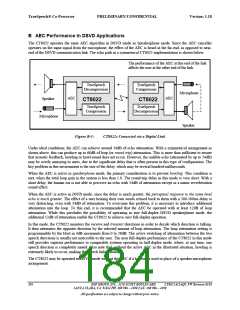
The CT8022 interacts with the external physical system via two CODECs. CODEC0 connects to the telephone line,
and CODEC1 connects to the microphone and speaker of the speakerphone. The input/output amplifiers (A1-A4 in
Figure A) should be configured to make best use of the CODECs dynamic range without introducing distortion or
clipping of the input/output signals. Care should be exercised in the design of the external circuits to avoid
undesirable cross talk between the various sections. The 4-to-2 wire coupling circuitry at the telephone line interface
should be designed to minimize the amount of the outgoing (to line) signal reflected (or echoed) back into the
incoming signal (from line). The amount of gain within the loop formed by the amplifiers A1-A4, the 4-to-2 wire
coupling, and the microphone-speaker acoustic linkage should be minimized.
The amplifier gains must be selected so that, when the voice signal comes from the microphone (and the telephone
line is silent), the signal level at the CODEC microphone input (CODEC1) is higher than the reflected signal level at
the CODEC line input (CODEC0). Further, when the voice signal originates from the telephone line, the input signal
at CODEC0 must be higher than the signal resulting from the acoustic echo present at the microphone CODEC1
input. This arrangement allows the CT8022 to determine at any time whether the microphone or line side is
speaking. The acoustic echo canceller is adjusted only when the CT8022 determines that the dominant signal is
coming from the telephone line side.
A.3
Acoustic System
The quality of the microphone and speaker has a direct effect on the attainable level of speakerphone performance.
Speech transducers that behave in a non-linear fashion introduce distortions into the signal that are not easy to cancel
out. The microphone and speaker should be operated within their linear ranges. Over-driving of either the
microphone of speaker must be avoided. It is possible to achieve significantly improved performance by eliminating
any physical coupling between the microphone and speaker. Ideally, the speaker and microphone should not be
housed within the same physical enclosure. Use of a freestanding speaker or microphone, separate from the main
system housing, is recommended. In a personal computer application, it is often possible to connect to the PC’s
existing sound system speakers via the auxiliary input of a sound card. Use of a freestanding external microphone is
often more convenient from the user’s point of view, since it allows more flexibility in positioning. Placing of the
microphone and speaker such that they are directly facing each other is not recommended. If microphone and
speaker are contained within the same physical housing, care should be taken to minimize the physical coupling
between them using acoustic isolation materials. In this situation, the physical coupling caused by the housing often
creates more feedback than the acoustic path. Physical enclosures often exhibit resonances at particular frequencies;
these should be damped as much as possible. It is also possible to reduce the effect of these resonances by electrical
filtering within the analog circuitry.
180
DSP GROUP, INC., 3120 SCOTT BOULEVARD CT8022A11AQC FW Revision 0118
SANTA CLARA, CA 95054 PH: 408 986 – 4300 FAX: 408 986 – 4490
All specifications are subject to change without prior notice.

 ETC [ ETC ]