AZ6961
RELAY ORDERING DATA
COIL SPECIFICATIONS
ORDER NUMBER*
Nominal Coil
VDC
Must Operate
VDC
Max. Continuous
VDC
Coil Resistance
Ohm
1 Form A
(SPST-NO)
1 Form C
(SPDT)
5
6
3.5
4.2
11.6
14.0
113 ± 10%
164 ± 10%
AZ6961–1A–5D
AZ6961–1C–5D
AZ6961–1C–6D
AZ6961–1C–9D
AZ6961–1C–12D
AZ6961–1C–15D
AZ6961–1C–24D
AZ6961–1C–48D
AZ6961–1C–60D
AZ6961–1A–6D
AZ6961–1A–9D
AZ6961–1A–12D
AZ6961–1A–15D
AZ6961–1A–24D
AZ6961–1A–48D
AZ6961–1A–60D
9
6.3
21.1
360 ± 10%
12
15
24
48
60
8.4
27.2
617 ± 10%
10.5
16.8
33.6
42.0
38.0
800 ± 10%
53.1
2,350 ± 10%
9,600 ± 15%
12,500 ± 15%
107.3
122.4
*
Add suffix “E” to “1A” or “1C” for silver tin oxide contacts. Add suffix “B” to “1A” or “1C” for silver nickel contacts.
Add suffix “E” at the end of order number for sealed version. Add suffix “A” for gold plated contacts.
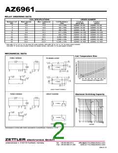
MECHANICAL DATA
Coil Temperature Rise
FORM C VERSION
PC BOARD LAYOUT
160
150
140
130
120
110
100
90
.062
[1.57]
1.132 Max.
[28.75]
.408 Max.
[10.35]
.870
[22.1]
5 x ø .051
[ø 1.3]
.050
[1.3]
.494 Max.
[12.55]
.298
[7.56]
1 FORM C
80
70
.126
[3.2]
.126
[3.2]
.012
[0.3]
60
.142
[3.6]
50
40
30
10A
%
20
3 x .016
[0.4]
0A
2 x ø .020
[ø 0.5]
10
.744
[18.9]
.116
[2.95]
4 x ø .051
[ø 1.3]
0
3 x .031
[0.8]
60
80%
100%
120%
140%
160%
180%
200%
220%
Percent of Nominal Coil Voltage at 20°C
.050
[1.3]
.298
[7.56]
1 FORM A
.198
[5.04]
VIEWED TOWARD TERMINALS
FORM A VERSION
CIRCUIT DIAGRAM
Maximum Switching Capacity
1.132 Max.
[28.75]
.408 Max.
[10.35]
10
.
0
9.0
8.0
7.0
1
4
6.0
5.0
DC Resistive
Load
.494 Max.
[12.55]
4.0
3.0
1 FORM C
2
3
5
2.0
AC Resistive
Load
.012
[0.3]
.142
[3.6]
1.
0
.9
.8
.7
2 x ø .020
[ø 0.5]
2 x .016
[0.4]
.6
.5
2 x .031
[0.8]
.4
.3
1
3
1 FORM A
.2
2
4
.1
VIEWED TOWARD TERMINALS
VOLTAGE
Dimensions in inches with metric equivalents in parentheses. Tolerance: ± .010"
ZETTLER electronics GmbH
Junkersstrasse 3, D-82178 Puchheim, Germany
Tel. +49 89 800 97 0
Fax +49 89 800 97 200
office@ZETTLERelectronics.com
www.ZETTLERelectronics.com
2004-07-29

 ZETTLER [ ZETTLER ELECTRONICS ]