MVTX2801
Data Sheet
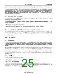
P7
P6
P5
P4
P3
P2
High Drop Low Drop
Level 1
N > 240
X%
0%
|P7| > A |P6| > B |P5| > C |P4| > D |P3| > E |P2| > F KB
KB KB KB KB KB
Level 2
N > 280
Y%
Z%
100%
Level 3
N > 320
100%
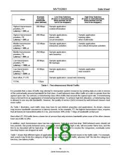
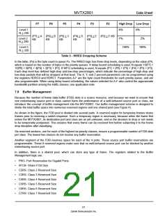
Table 3 - WRED Dropping Scheme
In the table, |Px| is the byte count in queue Px. The WRED logic has three drop levels, depending on the value of N,
which is based on the number of bytes in the priority queues. If delay bound scheduling is used, N equals 16|P7| +
16|P6| + 8|P5| + 4|P4| + 2|P3| + |P2|. If WFQ scheduling is used, N equals |P7| + |P6| + |P5| + |P4| + |P3| + |P2|.
Each drop level has defined high-drop and low-drop percentages, which indicate the percentage of high-drop and
low-drop packets that will be dropped at that level. The X, Y, and Z percent parameters can be programmed using
the registers RDRC0 and RDRC1. Parameters A-F are the byte count thresholds for each priority queue, and are
also programmable. When using delay bound scheduling, the values selected for A-F also control the approximate
bandwidth partition among the traffic classes; see application note.
7.8 Buffer Management
Because the number of frame data buffer (FDB) slots is a scarce resource, and because we want to ensure that
one misbehaving source port or class cannot harm the performance of a well-behaved source port or class, we
introduce the concept of buffer management into the MVTX2801. Our buffer management scheme is designed to
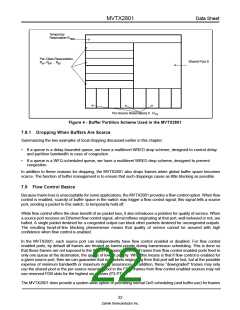
divide the total buffer space into numerous reserved regions and one shared pool (see Figure 4).
As shown in the figure, the FDB pool is divided into several parts. A reserved region for temporary frames stores
frames prior to receiving a switch response. Such a temporary region is necessary, because when the frame first
enters the MVTX2801, its destination port and class are as yet unknown, and so the decision to drop or not needs
to be temporarily postponed. This ensures that every frame can be received first before subjecting it to the frame
drop discipline after classifying.
Six reserved sections, one for each of the highest six priority classes, ensure a programmable number of FDB slots
per class. The lowest two classes do not receive any buffer reservation.
Another segment of the FDB reserves space for each of the 4 ports. These source port buffer reservations are
programmable. These 8 reserved regions make sure that no well-behaved source port can be blocked by another
misbehaving source port.
In addition, there is a shared pool, which can store any type of frame. The registers related to the Buffer
Management logic are:
•
•
•
•
•
•
•
•
PRG- Port Reservation for Gigabit Ports
SFCB- Share FCB Size
C2RS- Class 2 Reserved Size
C3RS- Class 3 Reserved Size
C4RS- Class 4 Reserved Size
C5RS- Class 5 Reserved Size
C6RS- Class 6 Reserved Size
C7RS- Class 7 Reserved Size
21
Zarlink Semiconductor Inc.

 ZARLINK [ ZARLINK SEMICONDUCTOR INC ]