MT88L70
Data Sheet
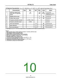
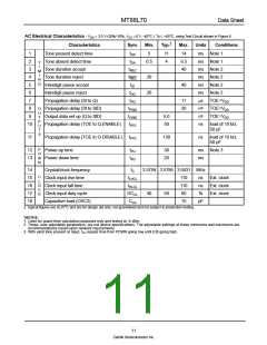
AC Electrical Characteristics - VDD = 3.0 V +20%/-10%, VSS = 0 V, -40°C ≤ TO ≤ +85°C, using Test Circuit shown in Fig. 6.
Characteristics
Sym
Min.
Typ‡
Max
Units
Notes*
1,2,3,5,6,9
1
Valid input signal levels
(each tone of composite
signal)
-34
-4.0
489
dBm
15.4
mVRMS Min @ VDD=3.6 V
Max @ VDD=2.7 V
2
3
4
5
6
7
8
Negative twist accept
Positive twist accept
Frequency deviation accept
Frequency deviation reject
Third zone tolerance
Noise tolerance
8
8
dB
dB
2,3,6,9,12
2,3,6,9,12
2,3,5,9
±1.5% ± 2 Hz
±3.5%
2,3,5,9
-16
-12
+22
dB
dB
dB
2,3,4,5,9,10
2,3,4,5,7,9,10
2,3,4,5,8,9,11
Dial zone tolerance
‡ Typical figures are at 25 °C and are for design aid only: not guaranteed and not subject to production testing.
*NOTES
1. dBm= decibels above or below a reference power of 1 mW into a 600 ohm load.
2. Digit sequence consists of all DTMF tones.
3. Tone duration= 40 ms, tone pause= 40 ms.
4. Signal condition consists of nominal DTMF frequencies.
5. Both tones in composite signal have an equal amplitude.
6. Tone pair is deviated by ±1.5%± 2 Hz.
7. Bandwidth limited (3 kHz) Gaussian noise.
8. The precise dial tone frequencies are (350 Hz and 440 Hz) ± 2%.
9. For an error rate of better than 1 in 10,000.
10. Referenced to lowest level frequency component in DTMF signal.
11. Referenced to the minimum valid accept level.
12. Guaranteed by design and characterization.
10
Zarlink Semiconductor Inc.

 ZARLINK [ ZARLINK SEMICONDUCTOR INC ]