MT88E43B
Data Sheet
1. Line Reversal Detection
Line reversal, or polarity reversal on the A and B wires indicates the arrival of an incoming CDS call, as specified in
SIN227. When the event (line reversal) occurs, TRIGin rises past the high going Schmitt threshold VT+ and
TRIGout, which is normally high, is pulled low. When the event is over, TRIGin falls back to below the low going
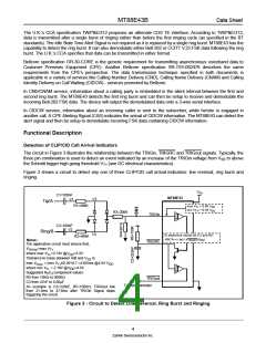
Schmitt threshold VT- and TRIGout returns high. The components R5 and C3 (see Figure 3) at TRIGRC ensure a
minimum TRIGout low interval.
In a TE designed for CLIP, the TRIGout high to low transition may be used to interrupt or wake-up the
microcontroller. The controller can thus be put into power-down mode to conserve power in a battery operated TE.
2. Ring Burst Detection
CCA does not support the dual tone alert signal (refer to Dual Tone Alert Signal Detection section). Instead, CCA
requires that the TE be able to detect a single burst of ringing (duration 200-450 ms) that precedes CLIP FSK data.
The ring burst may vary from 30 to 75 Vrms and is approximately 25 Hz.
Again in a TE designed for CCA CLIP, the TRIGout high to low transition may be used to interrupt or wake-up the
microcontroller. The controller can thus be put into power-down mode to conserve power in a battery operated TE.
3. Ring Detection
In Bellcore’s CND/CNAM scheme, the CID FSK data is transmitted between the first and second ringing cycles.
The circuit in Figure 3 will generate a ring envelope signal (active low) at TRIGout for a ring voltage of at least
40 Vrms. R5 and C3 filter the ring signal to provide an envelope output.
The diode bridge shown in Figure 3 works for both single ended and balanced ringing. A fraction of the ring voltage
is applied to the TRIGin input. When the voltage at TRIGin is above the Schmitt trigger high going threshold VT+,
TRIGRC is pulled low as C3 discharges. TRIGout stays low as long as the C3 voltage stays below the minimum
VT+
.
In a CPE designed for CND/CNAM, the TRIGout high to low transition may be used to interrupt or wake-up the
microcontroller. The controller can thus be put into power-down mode to conserve power.
If precise ring duration determination is critical, capacitor C3 in Figure 3 may be removed. The microcontroller will
now be able to time the ring duration directly. The result will be that TRIGout will be low only as long as the ringing
signal is present. Previously the RC time constant would cause only one interrupt.
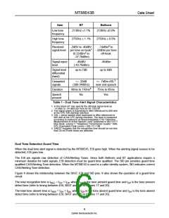
Dual Tone Alert Signal Detection
The BT on hook (idle state) caller ID scheme uses a dual tone alert signal whose characteristics are shown in Table
1.
Bellcore specifies a similar dual tone alert signal called CPE Alerting Signal (CAS) for use in off-hook data
transmission (see Table 1). Bellcore states that the CPE should be able to detect the CAS in the presence of near
end speech. The CAS detector should also be immune to imitation from near and far end speech.
In the MT88E43 the dual tone alert signal is separated into a high and a low tone by two bandpass filters. A
detection algorithm examines the two filter outputs to determine the presence of a dual tone alert signal. The ESt
pin goes high when both tones are present. Note that ESt is only a preliminary indication. The indication must be
sustained over the tone present guard time to be considered valid. Tone present and tone absent guard times can
be implemented with external RC components. The tone present guard time rejects signals of insufficient duration.
The tone absent guard time masks momentary detection dropout once the present guard time has been satisfied.
StD is the guard time qualified detector output.
5
Zarlink Semiconductor Inc.

 ZARLINK [ ZARLINK SEMICONDUCTOR INC ]