L9216B/H
Preliminary Data Sheet
September 2001
High-Voltage Ringing SLIC with Ground Start
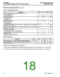
Electrical Characteristics (continued)
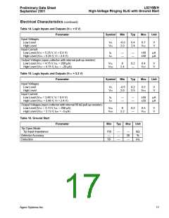
Table 17. Ringing Specifications
Parameter
Min
Typ
Max
Unit
RINGIN (This input is ac coupled through 0.47 µF.):
Input Voltage Swing
Input Impedance
0
—
—
100
VCC
—
V
kΩ
Ring Signal Isolation:
PT/PR to VITR
Ring Mode
—
60
—
dB
Ring Signal Isolation:
RINGIN to PT/PR
Nonring Mode
—
80
—
dB
Ringing Voltage (5 REN 1380 Ω + 40 µF load, 100 Ω loop, 2 x 50 Ω protection
resistors, –70 V battery)
40
40
—
—
—
—
Vrms
Vrms
Ringing Voltage (3 REN 2310 Ω + 24 µF load, 250 Ω loop, 2 x 50 Ω protection
resistors, –70 V battery)
Ring Signal Distortion:
5 REN 1380 Ω, 40 µF Load, 100 Ω Loop
3 REN 2310 Ω, 24 µF Load, 250 Ω Loop
—
—
3
3
—
—
%
%
Differential Gain:
RINGIN to PT/PR—No Load
—
55
—
—
Table 18. Ring Trip
Parameter
Min
Typ
Max
Unit
Ring Trip (NSTAT = 0): Loop Resistance (total) High Battery
Ring Trip (NSTAT = 1): Loop Resistance (total) High Battery
Trip Time (f = 20 Hz)
100
—
—
—
—
600
10
Ω
kΩ
ms
—
100
Ringing will not be tripped by the following loads:
■ 10 kΩ resistor in parallel with a 6 µF capacitor applied across tip and ring. Ring frequency = 17 Hz to 23 Hz.
■ 100 Ω resistor in series with a 2 µF capacitor applied across tip and ring. Ring frequency = 17 Hz to 23 Hz.
18
Agere Systems Inc.

 ZARLINK [ ZARLINK SEMICONDUCTOR INC ]