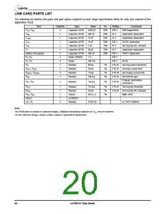
LINE CARD PARTS LIST
The following list defines the parts and part values required to meet target specification limits for only one channel of the
application circuit.
Item
Quantity
Type
Value
2200 pF
820 nF
10 nF
Tol.
20%
20%
20%
20%
10%
10%
20%
Rating
100 V
16 V
Comments
EMI Suppression
C
C
C
C
C
C
, C
BX
2
1
1
1
1
1
2
2
2
1
2
2
1
Capacitor (X7R)
Capacitor (X7R)
Capacitor (X7R)
Capacitor (X7R)
Capacitor (X7R)
Capacitor (X7R)
Capacitor (X7R)
Diode 1N400X
Diode
AX
Application dependent
Application dependent
DC/AC seperation
DC
DCR
HP
RT
T
16 V
18 nF
100 V
16 V
1 µF
Set ring trip RC constant
Application dependent
VBAT1 dependent
68 pF
100 nF
1 A
16 V
Battery Decoupling
D , D
100 V
100 V
100 V
1/10 W
1/10 W
1/10 W
1/10 W
3
4
2
D , D
100 mA
66 kΩ
50 kΩ
15 kΩ
250 kΩ
50 nS
1
R
Resistor
1%
1%
1%
1%
Set loop detect threshold
Set loop current Iimit
Set ringing current limit
Set 4W/2W gain
D
R
R
R
, R
DC2
Resistor
DC1
, R
Resistor
DCR1
RX
DCR2
Resistor
Program termination
impedance
R
, R
2
Resistor
125 kΩ
1%
1/10 W
T1
T2
R
R
R
1
1
Resistor
Resistor
715 kΩ
42 kΩ
1%
1%
1%
1/10 W
1/10 W
Set ring trip threshold
Set ring trip RC constant
MMC 9935
RT1
RT2
, R
1
1
2
Hybrid
Le79R101
Sidactor
50 Ω x 2
FA
FB
RSLIC
U2, U3
P100 ISC
or TISP 61089AD
Note:
The BOM above is based on balanced ringing. Additional decoupling capacitor on V may be required.
CC
For the reference design, please contact Legerity’s applications department.
20
Le79R101 Data Sheet

 ZARLINK [ ZARLINK SEMICONDUCTOR INC ]