GP2021
has two components, an analog path delay which varies
with temperature and component tolerances and a Digital
path delay which is constant if oscillator drift variations are
neglected.
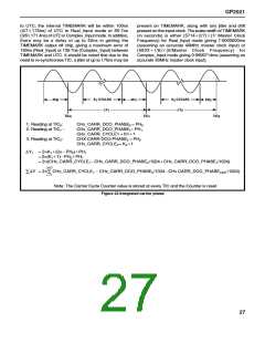
To this number, the fractional carrier cycle at the end has
to be added, and the fractional carrier cycle at the beginning
has to be subtracted. Both numbers are read from the
CHx_CARR_DCO_PHASE register. The total phase
change can be calculated as follows:
The digital delay is easier to estimate and is made up of
the following:
Integrated Carrier Phase =
In Real_lnput mode:
2p3S Numbers in Carrier Cycle Counter
1final Carrier DCO phase
2Initial Carrier DCO phase
1. The time from the sampling edge of the SIGN and MAG
bits in the front end (SAMPCLK) to the re-sampling in
the Sample Latch (175ns less the propagation delay of
SAMPCLK to the Front-end).
Fig. 22 shows how this equation is derived.
2. Plus the time for the correlation in the Correlator on
these same SIGN and MAG bits (125 ns).
3. Plus the delay in the accumulator to latch the sampled
data (175 ns ).
4. Less the time between the correlation and theTIC clock
phase which is before the accumulator latch phase (75
ns), Giving a total of 400 ns less the SAMPCLK delay.
This Integrated Carrier Phase may be related to the delta-
range (the change in distance to each satellite). When used
with the orbital parameters of the satellites, the delta ranges
give a measure of the receiver’s movement between fixes,
which is independent of those fixes and so can be used to
smooth them. It can also give a velocity directly. The delta
ranges will be noisy and most of the value is due to satellite
movement so the determination of velocity must use data
from adequately separated TlCs. For position smoothing
all delta ranges may be included in the input to the
navigation filter, as that filter will perform a running average
of the delta-ranges as well as the ranges.
In Complex_lnput mode:
1. The time for the correlation in the Correlator on theS IGN
and MAG bits after sampling (114 ns).
2. Plus the delay in the accumulator to latch the sampled
data (171ns).
3. Less the time between the correlation and theTIC clock
phase which is before the accumulator latch phase
(86ns), giving a total of 199ns.
Timemark Generation
The GP2021 is capable of generating an accurate
TIMEMARK timing output on one of the discrete outputs if
required. TIMEMARK is intended to be a UTC aligned
timing output with an accurate 1 second period and a pulse
width of 1 ms. The TIMEMARK output is always derived
from a rising edge on TIC, and for UTC aligned operation
the TIC counter must be brought into phase with UTC.
This is done by modifying the division ratio of the TIC
counter for a single TIC period by increasing or reducing
the division ratio, thus slewing the phase of TlC. Since the
TIC counter is incremented every 175ns which is not an
exact sub-multiple of 1 second it is also necessary to
continually monitor the relationship betweenTIC and UTC
to keep TIC in phase with UTC. Once TIC is in phase with
UTC, the TIMEMARK output can be derived fromTIC using
one of 2 methods both of which involves writing to
TIMEMARK_CONTROL:
The analog delay through the radio receiver is set by such
parameters as group delay in filters, which for the
bandwidths used for C/A code will be in the region of
1 to 2ms and so swamps the digital delay, but this can be
measured and corrected for.
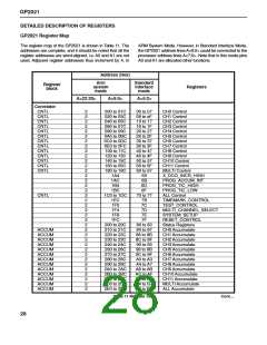
Integrated Carrier Phase Measurement
The Correlator tracking channel hardware allows
measurement of integrated carrier phase through the
CHx_CARRIER_CYCLE_HIGH and _LOW and the
CHx_CARRIER_DCO_PHASE registers, which are part
of the Measurement Data sampled at every TIC. The
CHx_CARRIER_CYCLE_HIGH and _LOW registers
contain the 20-bit number of positive-going zero crossings
of the Carrier DCO; this will be one more than the number
of full cycles elapsed (4 bits are in _HIGH and 16 in _LOW
register). The CHx_CARRIER_DCO_PHASE register
contains the cycle fraction or phase, with 10-bit resolution
to give 2p/1024 radian increments.
1. The GP2021 can be armed to produce a TIMEMARK
output at the next TIC only, or
2. It can be programmed to give aTIMEMARK output every
n TlCs starting at the next TIC.
To get the Integrated Carrier Phase over several TIC
periods all that is needed is to read the
CHx_CARRIER_CYCLE_HIGH and _LOW registers at
every TIC and sum the readings. This gives a number
1 higher than the number of complete carrier cycles, when
a carrier cycle is measured from one positive-going zero
crossing to the next.
A separate counter resets the TIMEMARK output giving a
1 ms pulse width. The TIC counter can be programmed
with an accuracy of 175ns in Real_lnput mode or 171.4ns
in Complex_lnput mode. This determines the accuracy of
the TIMEMARK output. If the TIC is continually
synchronised to keep the rising edge as close as possible
26

 ZARLINK [ ZARLINK SEMICONDUCTOR INC ]