YB1518
Step-up DC-DC Converter White LED Driver
Functional Block
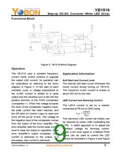
Figure 3: YB1518 Block Diagram
Operation
The YB1518 uses a constant frequency,
current mode control scheme to regulate
the output LED current. Its operation can
be understood by referring to the block
diagram in Figure 3. At the start of each
oscillator cycle, a voltage proportional to
the switch current is added to a ramp
output and the resulting sum is fed into the
positive terminal of the PWM comparator
(comparator-1). When this voltage exceeds
the level of the comparator negative input,
the peak current has been reached, and
the SR latch (in Control Logic) is reset and
turns off the power switch. The voltage at
the negative input of the comparator comes
from the output of the error amplifier. The
error amplifier sets the correct peak current
level to keep the output in regulation. If the
error amplifier’s output increases, more
current is delivered to the output; if it
decreases, less current is delivered.
Application Information
Soft Start and Current Limit
The internal soft start circuit minimizes the
inrush current during turning on YB1518.
The maximum switch current is limited to
about 450 mA by the chip.
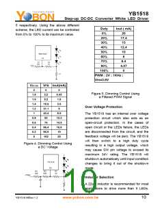
LED Current and Dimming Control
The LED’s current is set by a resistor
connected at FB pin to GND using:
100mV
ILED
=
RLED
The maximum LED current set initially can
be reduced by pulse width modulating the
CTRL. A better approach is to adjust the
feedback voltage for dimming control.
Either a DC level signal or a filtered PWM
signal can be used to control the LED
current as illustrated in Figure 4 and Figure
YB1518 MRev.1.2
www.yobon.com.tw
9

 YOBON [ YOBON TECHNOLOGIES,INC. ]