WM8976
Pre-Production
DESCRIPTION
REGISTER
ADDRESS
BIT
LABEL
LOUT1ZC
DEFAULT
R52
7
0
Headphone volume zero cross
enable:
LOUT1
1 = Change gain on zero cross only
0 = Change gain immediately
Left headphone output mute:
0 = Normal operation
1 = Mute
Volume
control
6
LOUT1MUTE
LOUT1VOL
0
5:0
111001
Left headphone output volume:
000000 = -57dB
...
111001 = 0dB
...
111111 = +6dB
8
7
HPVU
Not latched LOUT1 and ROUT1 volumes do not
update until a 1 is written to HPVU
(in reg 52 or 53)
R53
ROUT1ZC
0
Headphone volume zero cross
enable:
ROUT1
Volume
control
1 = Change gain on zero cross only
0 = Change gain immediately
Right headphone output mute:
0 = Normal operation
1 = Mute
6
ROUT1MUTE
ROUT1VOL
0
5:0
111001
Right headphone output volume:
000000 = -57dB
...
111001 = 0dB
...
111111 = +6dB
8
HPVU
Not latched LOUT1 and ROUT1 volumes do not
update until a 1 is written to HPVU
(in reg 52 or 53)
Table 39 OUT1 Volume Control
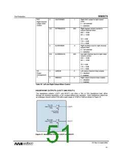
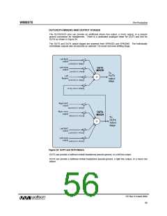
Headphone Output using DC Blocking Capacitors:
DC Coupled Headphone Output:
Figure 22 Recommended Headphone Output Configurations
When DC blocking capacitors are used, then their capacitance and the load resistance together
determine the lower cut-off frequency, fc. Increasing the capacitance lowers fc, improving the bass
response. Smaller capacitance values will diminish the bass response. Assuming a 16Ω load and
C1, C2 = 220µF:
fc = 1 / 2π RLC1 = 1 / (2π x 16Ω x 220µF) = 45 Hz
PP Rev 3.0 April 2006
52
w

 WOLFSON [ WOLFSON MICROELECTRONICS PLC ]