WM8976
Pre-Production
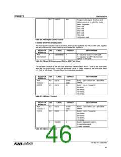
Programmable signal threshold level
6:4
LIMLVL
000
(determines level at which the limiter
starts to operate)
000=-1dB
001=-2dB
010=-3dB
011=-4dB
100=-5dB
101 to 111=-6dB
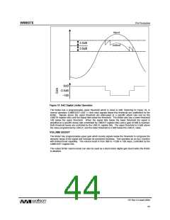
Table 29 DAC Digital Limiter Control
5-BAND GRAPHIC EQUALISER
A 5-band graphic equaliser (EQ) is provided, which can be applied to the ADC or DAC path, together
with 3D enhancement, under control of the EQ3DMODE register bit.
REGISTER
ADDRESS
BIT
LABEL
DEFAULT
DESCRIPTION
R18
EQ Control 1
8
EQ3DMODE
1
0 = Equaliser applied to ADC path
1 = Equaliser and 3D Enhancement
applied to DAC path
Table 30 EQ and 3D Enhancement DAC or ADC Path Select
The equaliser consists of low and high frequency shelving filters (Band 1 and 5) and three peak
filters for the centre bands. Each has adjustable cut-off or centre frequency, and selectable boost
(+/- 12dB in 1dB steps). The peak filters have selectable bandwidth.
REGISTER
ADDRESS
BIT
LABEL
EQ1G
EQ1C
DEFAULT
DESCRIPTION
R18
4:0
01100
(0dB)
01
Band 1 Gain Control. See Table 36 for
details.
EQ Band 1
Control
6:5
Band 1 Cut-off Frequency:
00=80Hz
01=105Hz
10=135Hz
11=175Hz
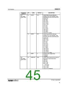
Table 31 EQ Band 1 Control
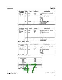
REGISTER
ADDRESS
BIT
LABEL
EQ2G
DEFAULT
DESCRIPTION
R19
4:0
01100
(0dB)
01
Band 2 Gain Control. See Table 36 for
details.
EQ Band 2
Control
6:5
EQ2C
Band 2 Centre Frequency:
00=230Hz
01=300Hz
10=385Hz
11=500Hz
8
EQ2BW
0
Band 2 Bandwidth Control
0=narrow bandwidth
1=wide bandwidth
Table 32 EQ Band 2 Control
PP Rev 3.0 April 2006
46
w

 WOLFSON [ WOLFSON MICROELECTRONICS PLC ]