WM8741
Product Preview
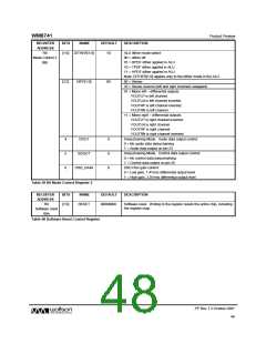
REGISTER
ADDRESS
R8
BITS
NAME
DEFAULT
DESCRIPTION
[1:0] DITHER[1:0]
10
ALU dither mode select:
Mode Control 2
08h
00 = dither off
01 = RPDF dither applied in ALU
10 = TPDF dither applied in ALU
11 = HPDF dither applied in ALU
Note: DITHER[1:0] applies only to the dither mode in the ALU.
00 = Stereo
[3:2]
DIFF[1:0]
00
10 = Stereo reverse (left and right channels swapped)
01 = Mono left – differential outputs
VOUTLP is left channel.
VOUTLN is left channel inverted.
VOUTRP is left channel inverted.
VOUTRN is left channel.
11 = Mono right – differential outputs.
VOUTLP is right channel inverted.
VOUTLN is right channel.
VOUTRP is right channel.
VOUTRN is right channel inverted.
Daisychaining Mode. Audio data output control:
0 = No audio data daisychaining
1 = Audio data output on pin 23
4
5
6
DOUT
SDOUT
0
0
0
Daisychaining Mode. Control data output control:
0 = No control data daisychaining
1 = Control data output on pin 25
DSD Plus gain control:
DSD_GAIN
0 = Low gain, 1.4Vrms differential output level
1 = High gain, 2.0Vrms differential output level
Table 59 R8 Mode Control Register 2
REGISTER
ADDRESS
R9
BITS
NAME
DEFAULT
DESCRIPTION
[7:0]
RESET
00000000
Software reset. Writing to the register resets the entire chip, including
the register map.
Software reset
09h
Table 60 Software Reset Control Register
PP Rev 1.3 October 2007
48
w

 WOLFSON [ WOLFSON MICROELECTRONICS PLC ]