Product Preview
WM8741
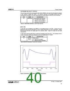
DSD MUTE CONTROL
In DSD Direct mode, an analogue mute can be applied at the output of the DAC. This is controlled
by register bit AMUTE.
REGISTER ADDRESS
BIT
LABEL
DEFAULT
DESCRIPTION
DSD Direct mute control:
0 = mute off
R4
Volume Control
04h
7
AMUTE
0
1 = mute on
Table 40 DSD Analogue Mute Control
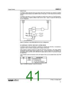
POWER SAVING STANDBY CONTROL
Setting the PWDN register bit immediately connects all outputs to VMID and resets the digital sections
of the DAC system including the DLL, the audio interface and the DSP. Input data samples are not
preserved, but all control register settings are maintained. When PWDN is cleared the WM8741 will
repeat its power-on initialisation sequence.
REGISTER ADDRESS
BIT
LABEL
DEFAULT
DESCRIPTION
Power Down Mode Select:
0 = Normal Mode
R5
Format Control
05h
7
PWDN
0
1 = Power Down Mode
Table 41 Powerdown Control
HARDWARE CONTROL MODE
When the MODE pin is held ‘low’ the WM8741 is set to hardware control mode and a limited feature
set can be configured.
PIN
NAME
MODE/
LRSEL
DESCRIPTION
24
0 = Hardware control mode
1 = 3-wire serial control mode
Z = 2-wire serial control mode
Table 42 MODE/LRSEL Hardware Control Pin Function
DSD AND PCM MODE SWITCHING
The audio interface mode can be switched between DSD Direct and PCM by controlling the state of
pin DSD. It is recommended that the chip is forced into a MUTE state before dynamically switching
modes.
PIN
NAME
SCLK/DSD 0 = PCM Mode
1 = DSD Direct Mode
DESCRIPTION
27
Table 43 SCLK/DSD Hardware Control Pin Function
AUDIO INPUT FORMAT
Under hardware control, it is possible to select between four different modes of operation for the
PCM audio interface.
PIN NUMBER
NAME
28
23
DESCRIPTION
16-bit right justified
24-bit right justified
24-bit left justified
24-bit I2S
CSB/SADDR/I2S
IWO/DOUT
STATUS
0
0
1
1
0
1
0
1
Table 44 CSB/SADDR/I2S and IWO/DOUT Hardware Control Pin Function
PP Rev 1.3 October 2007
39
w

 WOLFSON [ WOLFSON MICROELECTRONICS PLC ]